Lexus NX: LED Headlight LH Circuit Malfunction (B2430,B2431)
DESCRIPTION
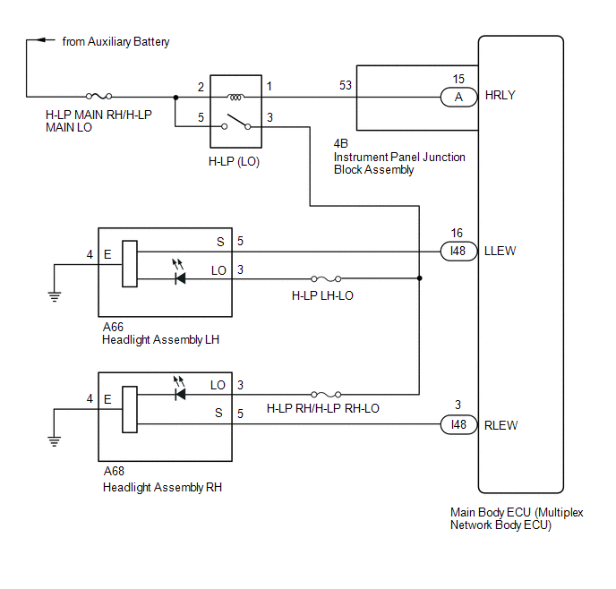
The illumination of the low beam headlights is controlled by the main body ECU (multiplex network body ECU). When the headlights are turned on, the main body ECU (multiplex network body ECU) receives a signal from the headlight assembly and detects the illumination condition of the low beam headlights.
| DTC No. | Detection Item | DTC Detection Condition | Trouble Area |
|---|---|---|---|
| B2430 | LED Headlight LH Circuit Malfunction | LED headlight LH circuit malfunction |
|
| B2431 | LED Headlight RH Circuit Malfunction | LED headlight RH circuit malfunction |
|
HINT:
DTC B2430 and B2431 are not output if 12 seconds have not elapsed since the power switch was turned on (IG).
WIRING DIAGRAM
CAUTION / NOTICE / HINT
NOTICE:
- Inspect the fuses for circuits related to this system before performing the following procedure.
- Recognition code registration is necessary when replacing the main body ECU (multiplex network body ECU).
- If the main body ECU (multiplex network body ECU) is replaced, refer to Registration.
PROCEDURE
| 1. | CLEAR DTC |
(a) Clear the DTCs.
Click here .gif)
|
.gif)
| 2. | CHECK FOR DTC |
(a) Check for DTCs.
Click here
OK:
DTC B2430 or B2431 output does not occur.
| OK | .gif) | USE SIMULATION METHOD TO CHECK |
|
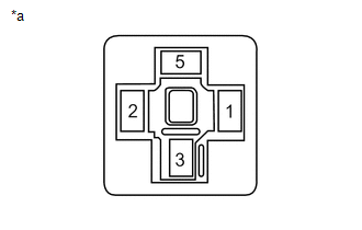
| 3. | CHECK HEADLIGHT RELAY (H-LP [LO]) |
(a) Remove the headlight relay (H-LP LO) from the No. 2 engine room relay block.
(b) Inspect the headlight light relay (H-LP LO).
| NG | | REPLACE HEADLIGHT RELAY (H-LP LO) |
|
| 4. | CHECK HARNESS AND CONNECTOR (HEADLIGHT RELAY [H-LP (LO)] - BATTERY) |
| (a) Remove the headlight relay (H-LP [LO]) from the No. 2 engine room relay block. |
|
(b) Measure the voltage according to the value(s) in the table below.
Standard Voltage:
| Tester Connection | Switch Condition | Specified Condition |
|---|---|---|
| Relay terminal 5 - Body ground | Power switch off | 11 to 14 V |
| Relay terminal 2 - Body ground | Power switch off | 11 to 14 V |
| NG | | REPAIR OR REPLACE HARNESS OR CONNECTOR |
|
| 5. | CHECK HARNESS AND CONNECTOR (HEADLIGHT RELAY [H-LP (LO)] - INSTRUMENT PANEL JUNCTION BLOCK ASSEMBLY) |
(a) Remove the headlight relay (H-LP [LO]) from the No. 2 engine room relay block.
(b) Disconnect the 4B instrument panel junction block assembly connector.
(c) Measure the resistance according to the value(s) in the table below.
Standard Resistance:
| Tester Connection | Condition | Specified Condition |
|---|---|---|
| Relay terminal 1 - 4B-53 | Always | Below 1 Ω |
| Relay terminal 1 or 4B-53 - Body ground | Always | 10 kΩ or higher |
| NG | | REPAIR OR REPLACE HARNESS OR CONNECTOR |
|
| 6. | INSPECT INSTRUMENT PANEL JUNCTION BLOCK ASSEMBLY |
| (a) Remove the instrument panel junction block assembly. Click here |
|
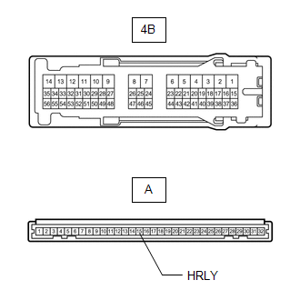
(b) Remove the main body ECU (multiplex network body ECU) from the instrument panel junction block assembly.
Click here
(c) Measure the resistance according to the value(s) in the table below.
Standard Resistance:
| Tester Connection | Condition | Specified Condition |
|---|---|---|
| A-15 (HRLY) - 4B-53 | Always | Below 1 Ω |
| NG | | REPLACE INSTRUMENT PANEL JUNCTION BLOCK ASSEMBLY |
|
| 7. | CHECK HARNESS AND CONNECTOR (HEADLIGHT RELAY [H-LP (LO)] - HEADLIGHT ASSEMBLY) |
- *1: for LH
- *2: for RH
(a) Remove the headlight relay (H-LP [LO]) from the No. 2 engine room relay block.
(b) Disconnect the A66*1 and A68*2 headlight assembly connector.
(c) Measure the resistance according to the value(s) in the table below.
Standard Resistance:
for LH
| Tester Connection | Condition | Specified Condition |
|---|---|---|
| Relay terminal 3 - A66-3 (LO) | Always | Below 1 Ω |
| Headlight relay terminal 3 - Body ground | Always | 10 kΩ or higher |
for RH
| Tester Connection | Condition | Specified Condition |
|---|---|---|
| Relay terminal 3 - A68-3 (LO) | Always | Below 1 Ω |
| Headlight relay terminal 3 - Body ground | Always | 10 kΩ or higher |
| NG | | REPAIR OR REPLACE HARNESS OR CONNECTOR |
|
| 8. | CHECK HARNESS AND CONNECTOR (HEADLIGHT ASSEMBLY - MAIN BODY ECU [MULTIPLEX NETWORK BODY ECU] AND BODY GROUND) |
(a) Disconnect the A66*1 or A68*2 headlight assembly connector.
- *1: for LH
- *2: for RH
(b) Disconnect the I48 main body ECU (multiplex network body ECU) connector.
(c) Measure the resistance according to the value(s) in the table below.
Standard Resistance:
for LH
| Tester Connection | Condition | Specified Condition |
|---|---|---|
| A66-5 (S) - I48-16 (LLEW) | Always | Below 1 Ω |
| A66-4 (E) - Body ground | Always | Below 1 Ω |
| A66-5 (S) - Body ground | Always | 10 kΩ or higher |
for RH
| Tester Connection | Condition | Specified Condition |
|---|---|---|
| A68-5 (S) - I48-3 (RLEW) | Always | Below 1 Ω |
| A68-4 (E) - Body ground | Always | Below 1 Ω |
| A68-5 (S) - Body ground | Always | 10 kΩ or higher |
| NG | | REPAIR OR REPLACE HARNESS OR CONNECTOR |
|
| 9. | CHECK HEADLIGHT ASSEMBLY |
(a) Temporarily replace the headlight assembly with a new or normally functioning one.
(b) Check for DTCs.
Click here
OK:
DTC B2430 or B2431 output does not occur.
| OK | | END (REPLACE HEADLIGHT ASSEMBLY) |
| NG | | REPLACE MAIN BODY ECU (MULTIPLEX NETWORK BODY ECU) |
READ NEXT:
 Lost Communication with Multi-axis Acceleration Sensor Module Missing Message (U012587,U012987,U014087,U029387)
DESCRIPTION DTC No. Detection Item DTC Detection Condition Trouble Area DTC Output from U012587 Lost Communication with Multi-axis Acceleration Sensor Module Missing Message Communi
Lost Communication with Cruise Control Front Distance Range Sensor Missing Message (U023587)
DESCRIPTION DTC No. Detection Item DTC Detection Condition Trouble Area DTC Output from Note U023587 Lost Communication with Cruise Control Front Distance Range Sensor Missing Messa
Turn Signal Switch Circuit
DESCRIPTION The combination meter receives the turn signal switch information and controls the turn signal lights. WIRING DIAGRAM CAUTION / NOTICE / HINT NOTICE: When replacing the combination meter
SEE MORE:
Removal
REMOVAL CAUTION / NOTICE / HINT NOTICE:
Do not replace the spiral with sensor cable sub-assembly with the battery connected and the engine switch on (IG).
Do not rotate the spiral with sensor cable sub-assembly when the following conditions are met: 1) The steering wheel is removed, 2) the batt
How To Proceed With Troubleshooting
CAUTION / NOTICE / HINT HINT:
Use the following procedure to troubleshoot the headup display system.
*: Use the Techstream.
PROCEDURE 1. VEHICLE BROUGHT TO WORKSHOP
NEXT 2. CUSTOMER PROBLEM ANALYSIS
NEXT 3. INSPECT AUXILIARY BATTE
