Lexus NX: Lost Communication with Rear Gate Module (U0230)
DESCRIPTION
| DTC No. | Detection Item | DTC Detection Condition | Trouble Area | DTC Output from |
|---|---|---|---|---|
| U0230 | Lost Communication with Rear Gate Module | There is no communication from the multiplex network door ECU. |
| Main Body |
For vehicles with a power back door system.
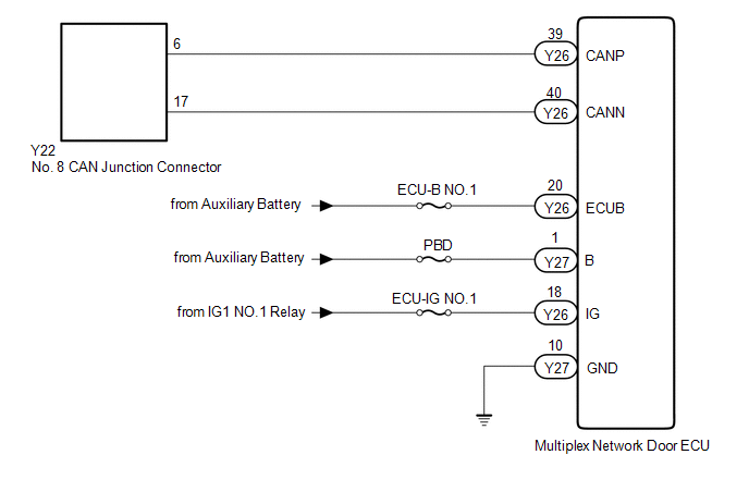
WIRING DIAGRAM
CAUTION / NOTICE / HINT
NOTICE:
- Inspect the fuses for circuits related to this system before performing the following inspection procedure.
- Before measuring the resistance of the CAN bus, turn the power switch off and leave the vehicle for 1 minute or more without operating the key, switches or opening or closing the doors. After that, disconnect the cable from the negative (-) auxiliary battery terminal and leave the vehicle for 1 minute or more before measuring the resistance.
-
After turning the power switch off, waiting time may be required before disconnecting the cable from the negative (-) auxiliary battery terminal.
Click here
.gif)
-
When disconnecting and reconnecting the auxiliary battery.
Click here
HINT:
When disconnecting and reconnecting the auxiliary battery, there is an automatic learning function that completes learning when the respective system is used.
Click here
-
Some parts must be initialized and set when replacing or removing and installing parts.
Click here
-
Because the order of diagnosis is important to allow correct diagnosis, make sure to begin troubleshooting using How to Proceed with Troubleshooting when CAN communication system related DTCs are output.
Click here
-
After performing repairs, perform the DTC check procedure and confirm that the DTCs are not output again.
DTC check procedure: Turn the power switch on (IG) and wait at least 20 seconds.
-
After the repair, perform CAN Bus Check and check that all the ECUs and sensors connected to the CAN communication system are displayed.
Click here
HINT:
- Operating the power switch, any switches or any doors triggers related ECU and sensor communication with the CAN, which causes resistance variation.
- Even after DTCs are cleared, if a DTC is stored again after driving the vehicle for a while, the malfunction may be occurring due to vibration of the vehicle. In such a case, wiggling the ECUs or wire harness while performing the inspection below may help determine the cause of the malfunction.
PROCEDURE
| 1. | CHECK FOR DTC |
(a) Check for DTCs.
Body Electrical > Main Body > Trouble CodesHINT:
If DTC U1002 is output from the gateway of the main body ECU (multiplex network body ECU), this indicates a sub bus 1 malfunction. Troubleshoot for DTC U1002 and check for malfunctions in sub bus 1.
| Result | Proceed to |
|---|---|
| DTC U1002 is not output from main body ECU (multiplex network body ECU) | A |
| DTC U1002 is output from main body ECU (multiplex network body ECU) | B |
| B | .gif) | GO TO DIAGNOSIS PROCEDURE INDICATED BY OUTPUT DTC |
|
.gif)
| 2. | CHECK FOR OPEN IN CAN BUS WIRE (MULTIPLEX NETWORK DOOR ECU BRANCH WIRE) |
| (a) Disconnect the cable from the negative (-) auxiliary battery terminal. |
|
(b) Disconnect the multiplex network door ECU connector.
(c) Measure the resistance according to the value(s) in the table below.
Standard Resistance:
| Tester Connection | Condition | Specified Condition |
|---|---|---|
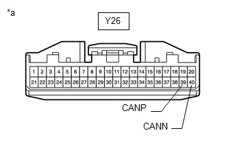
| Y26-39 (CANP) - Y26-40 (CANN) | Cable disconnected from negative (-) auxiliary battery terminal | 54 to 69 Ω |
| NG | | REPAIR OR REPLACE CAN BRANCH WIRE OR CONNECTOR (MULTIPLEX NETWORK DOOR ECU) |
|
| 3. | CHECK HARNESS AND CONNECTOR (MULTIPLEX NETWORK DOOR ECU - BATTERY AND BODY GROUND) |
| (a) Reconnect the cable to the negative (-) auxiliary battery terminal. |
|
(b) Disconnect the multiplex network door ECU connector.
(c) Measure the voltage according to the value(s) in the table below.
Standard Voltage:
| Tester Connection | Switch Condition | Specified Condition |
|---|---|---|
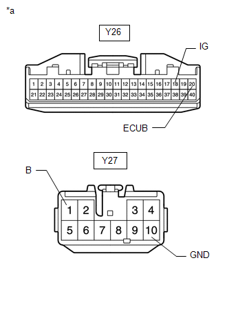
| Y26-20 (ECUB) - Body ground | Power switch off | 11 to 14 V |
| Y27-1 (B) - Body ground | Power switch off | 11 to 14 V |
| Y26-18 (IG) - Body ground | Power switch on (IG) | 11 to 14 V |
(d) Measure the resistance according to the value(s) in the table below.
Standard Resistance:
| Tester Connection | Condition | Specified Condition |
|---|---|---|
| Y27-10 (GND) - Body ground | Always | Below 1 Ω |
| OK | | REPLACE MULTIPLEX NETWORK DOOR ECU |
| NG | | REPAIR OR REPLACE HARNESS OR CONNECTOR |
READ NEXT:
 Lost Communication with Gateway Module (Main Body ECU) (U1002)
DESCRIPTION
The main body ECU (multiplex network body ECU) will store this DTC when no signals can be received from the ECUs that have been memorized as those that are connected to sub bus 1.
Whe
Lost Communication with Tilt & (U1115)
DESCRIPTION DTC No. Detection Item DTC Detection Condition Trouble Area DTC Output from U1115 Lost Communication with Tilt & Telescopic Module There is no communication from the
Hybrid Vehicle Control ECU Communication Stop Mode
DESCRIPTION Detection Item Symptom Trouble Area Hybrid Vehicle Control ECU Communication Stop Mode Any of the following conditions are met:
Communication stop for "Hybrid Vehicle Contr
SEE MORE:
Key-off Operation Function Operates even if Operating Conditions are not Satisfied
DESCRIPTION
When the front doors are closed, each power window regulator motor assembly can control its power window operation for approximately 43 seconds after the power switch is turned from on (IG) to off by receiving operation permission signals from the main body ECU (multiplex network body
Problem Symptoms Table
PROBLEM SYMPTOMS TABLE NOTICE:
The following inspection procedures for the parking assist monitor system are based on the assumption that the navigation system is normal. If the navigation system has any malfunctions, first proceed with troubleshooting the navigation system.
Click here
Depend
