Lexus NX: Manual(sos)switch
Inspection
INSPECTION
PROCEDURE
1. REMOVE MAP LIGHT ASSEMBLY
Click here .gif)
2. INSPECT MAP LIGHT ASSEMBLY
(a) Check the resistance.
(1) Measure the resistance according to the value(s) in the table below.
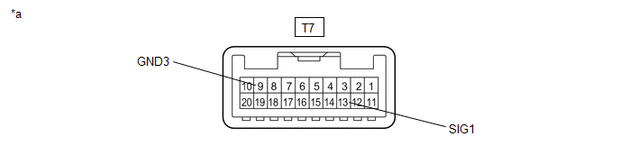
| *a | Component without harness connected (Map Light Assembly) | - | - |
Resistance:
| Tester Connection | Condition | Specified Condition |
|---|---|---|
| T7-13 (SIG1) - T7-9 (GND3) | Mayday switch not pressed | 410 to 414 Ω |
| T7-13 (SIG1) - T7-9 (GND3) | Mayday switch pressed | 81 to 83 Ω |
(b) Check the operation (indicator).
(1) Check that each indicator illuminates when 2 dry cell batteries are connected to the map light assembly connector terminals as shown in the illustration.
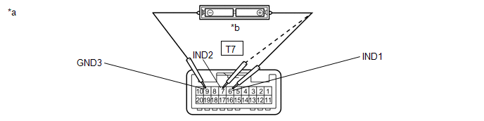
| *a | Component without harness connected (Map Light Assembly) | *b | Two 1.5 V dry cell batteries |
NOTICE:
Do not apply more than 3 V.
OK:
| Tester Connection | Condition | Specified Condition |
|---|---|---|
| T7-6 (IND1) - T7-9 (GND3) | Positive (+) dry cell battery - Negative (-) dry cell battery | HELP RED indicator illuminates |
| T7-7 (IND2) - T7-9 (GND3) | Positive (+) dry cell battery - Negative (-) dry cell battery | HELP GREEN indicator illuminates |
(c) Check that the HELP indicator illuminates when the battery is connected to the map light assembly connector terminals as shown in the illustration.

| *a | Component without harness connected (Map Light Assembly) | - | - |
OK:
| Tester Connection | Condition | Specified Condition |
|---|---|---|
| T7-5 (RRID) - T7-9 (GND3) | Positive (+) battery terminal - Negative (-) battery terminal | HELP indicator illuminates |
3. INSTALL MAP LIGHT ASSEMBLY
Click here
READ NEXT:
 Components
COMPONENTS ILLUSTRATION *1 DECK FLOOR BOX LH *2 NO. 3 DECK BOARD SUB-ASSEMBLY *3 REAR DECK FLOOR BOX *4 NEGATIVE AUXILIARY BATTERY TERMINAL N*m (kgf*cm, ft.*lbf): Specified
Removal
REMOVAL PROCEDURE 1. REMOVE DECK BOARD ASSEMBLY Click here 2. REMOVE NO. 3 DECK BOARD SUB-ASSEMBLY Click here 3. REMOVE REAR DECK FLOOR BOX Click here 4. REMOVE DECK FLOOR BOX LH Click here 5.
SEE MORE:
Outside rear view mirrors
For safe driving, adjust the mirror
angles to secure visibility before
driving.
WARNING
■When driving the vehicle
Observe the following precautions while
driving.
Failure to do so may result in loss of control
of the vehicle and cause an accident,
resulting in death or serious injury.
Hybrid Battery Precharge Contactor Circuit Stuck Closed (P0AE2-773)
DTC SUMMARY MALFUNCTION DESCRIPTION The hybrid vehicle control ECU detects a stuck closed malfunction of a precharge relay stuck malfunction on the HV battery negative side. The cause of this malfunction may be one of the following: Inside of inverter voltage sensor (VH) circuit malfunction
Volta
