Lexus NX: Mute Signal Circuit between Stereo Component Amplifier and Telematics Transceiver
DESCRIPTION
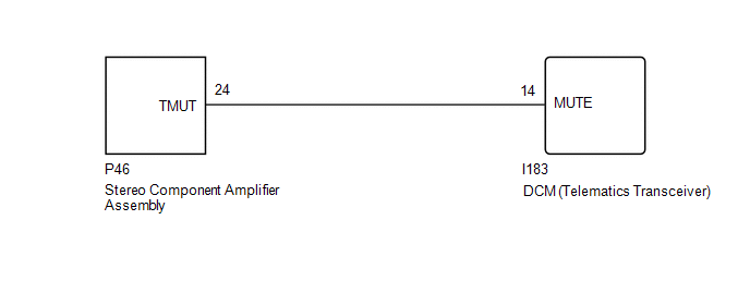
This DCM (telematics transceiver) sends a mute signal to the stereo component amplifier assembly. The stereo component amplifier assembly controls the volume according to the mute signal from the DCM (telematics transceiver).
If there is an open in the circuit, noise can be heard from the speakers when changing the sound source.
If there is a short in the circuit, even though the stereo component amplifier assembly is functioning normally, no sound or only an extremely faint sound can be heard.
WIRING DIAGRAM
CAUTION / NOTICE / HINT
NOTICE:
When replacing the DCM (telematics transceiver), make sure to replace it with a new one.
HINT:
Depending on the parts that are replaced during vehicle inspection or maintenance, performing initialization, registration or calibration may be needed. Refer to Precaution for Audio and Visual System.
Click here .gif)
PROCEDURE
| 1. | CHECK DCM (TELEMATICS TRANSCEIVER) |
| (a) Remove the DCM (telematics transceiver) with the connector(s) still connected. Click here |
|
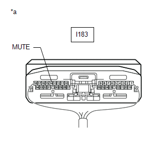
(b) Measure the voltage according to the value(s) in the table below.
Standard Voltage:
| Tester Connection | Condition | Specified Condition |
|---|---|---|
| I183-14 (MUTE) - Body ground | Power switch on (IG), audio system playing → Emergency call mode | 3.0 to 5.0 V → Below 1 V |
| OK | .gif) | PROCEED TO NEXT SUSPECTED AREA SHOWN IN PROBLEM SYMPTOMS TABLE |
|
.gif)
| 2. | CHECK HARNESS AND CONNECTOR (STEREO COMPONENT AMPLIFIER ASSEMBLY - DCM [TELEMATICS TRANSCEIVER]) |
(a) Disconnect the P46 stereo component amplifier assembly connector.
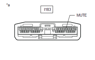
(b) Disconnect the I183 DCM (telematics transceiver) connector.
(c) Measure the resistance according to the value(s) in the table below.
Standard Resistance:
| Tester Connection | Condition | Specified Condition |
|---|---|---|
| P46-24 (TMUT) - I183-14 (MUTE) | Always | Below 1 Ω |
| P46-24 (TMUT) - Body ground | Always | 10 kΩ or higher |
| NG | | REPAIR OR REPLACE HARNESS OR CONNECTOR |
|
| 3. | CHECK STEREO COMPONENT AMPLIFIER ASSEMBLY |
(a) Disconnect the DCM (telematics transceiver) connector.
| (b) Measure the voltage according to the value(s) in the table below. Standard Voltage:
|
|
| OK | | REPLACE DCM (TELEMATICS TRANSCEIVER) |
| NG | | REPLACE STEREO COMPONENT AMPLIFIER ASSEMBLY |
READ NEXT:
 AVC-LAN Circuit
DESCRIPTION Each audio system component connected to the AVC-LAN (communication bus) transfers switch signals using the audio visual communication local area network. If a short to +B or short to grou
Vehicle Speed Signal Circuit between Stereo Component Amplifier and Combination Meter
DESCRIPTION The stereo component amplifier assembly receives a vehicle speed signal from the combination meter assembly to control the ASL function. HINT:
A voltage of 12 V or 5 V is output from ea
Voice Guidance Circuit between Radio Receiver and Stereo Component Amplifier
DESCRIPTION This circuit is used when the voice switch of the steering pad switch assembly is pushed. Using this circuit, the radio and display receiver assembly sends signals to the stereo component
SEE MORE:
Removal
REMOVAL PROCEDURE 1. REMOVE REAR SEAT ASSEMBLY (for Manual Seat) Click here 2. REMOVE REAR SEAT ASSEMBLY (for Power Seat) Click here 3. REMOVE TONNEAU COVER ASSEMBLY Click here 4. REMOVE DECK BOARD ASSEMBLY Click here 5. REMOVE NO. 2 DECK BOARD SUB-ASSEMBLY Click here 6. REMOVE
On-vehicle Inspection
ON-VEHICLE INSPECTION PROCEDURE 1. VISUALLY INSPECT HOSES, CONNECTIONS AND GASKETS (a) Visually check that the hoses, connections and gaskets have no cracks, leaks or damage. NOTICE:
Detachment or other problems with the engine oil dipstick, oil filler cap sub-assembly, PCV hose and other compone
