Lexus NX: Odo/Trip Switch Malfunction
DESCRIPTION
The ODO/TRIP display of the combination meter changes each time the trip switch is pressed.
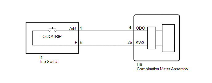
WIRING DIAGRAM
CAUTION / NOTICE / HINT
NOTICE:
When replacing the combination meter assembly, make sure to replace it with a new one.
PROCEDURE
| 1. | READ VALUE USING TECHSTREAM (ODO/TRIP CHANGE SW) |
(a) Using the Techstream, read the Data List.
Click here .gif)
| Tester Display | Measurement Item | Range | Normal Condition | Diagnostic Note |
|---|---|---|---|---|
| ODO/TRIP Change SW | ODO/TRIP switch | OFF or ON | OFF: ODO/TRIP switch released ON: ODO/TRIP switch pushed | - |
| Tester Display |
|---|
| ODO/TRIP Change SW |
OK:
ODO/TRIP switch condition displayed on the Techstream changes with the actual switch operation.
| OK | .gif) | REPLACE COMBINATION METER ASSEMBLY |
|
.gif)
| 2. | INSPECT TRIP SWITCH |
(a) Remove the trip switch.
Click here
(b) Inspect the trip switch.
Click here
| NG | | REPLACE TRIP SWITCH |
|
| 3. | CHECK HARNESS AND CONNECTOR (COMBINATION METER ASSEMBLY - TRIP SWITCH) |
(a) Disconnect the I10 combination meter assembly connector.
(b) Disconnect the I1 trip switch connector.
(c) Measure the resistance according to the value(s) in the table below.
Standard Resistance:
| Tester Connection | Condition | Specified Condition |
|---|---|---|
| I10-4 (ODO) - I1-4 (A/B) | Always | Below 1 Ω |
| I10-26 (SW3) - I1-5 (E) | Always | Below 1 Ω |
| I10-4 (ODO) or I1-4 (A/B) - Body ground | Always | 10 kΩ or higher |
| I10-26 (SW3) or I1-5 (E) - Body ground | Always | 10 kΩ or higher |
| OK | | REPLACE COMBINATION METER ASSEMBLY |
| NG | | REPAIR OR REPLACE HARNESS OR CONNECTOR |
READ NEXT:
 Operating Light Control Rheostat does not Change Light Brightness
DESCRIPTION The combination meter assembly receives signals from this circuit to adjust the illumination of the combination meter assembly. The combination meter assembly sets the illumination level b
Speed Signal Circuit
DESCRIPTION The combination meter assembly receives the vehicle speed signal from this circuit. The wheel speed sensors produce an output that varies according to the vehicle speed. The wheel speed se
SEE MORE:
Noise Occurs
PROCEDURE 1. CHECK NOISE CONDITION (a) Check from which direction the noise comes (front left or right, or rear left or right). OK: The location of the noise source can be determined. NG GO TO STEP 3
OK 2. CHECK SPEAKERS (a) Check the installation condi
IG Power Supply Voltage (C1551)
DESCRIPTION The power steering ECU assembly distinguishes the power switch status as on (IG) or off through the IG power source circuit. DTC No. Detection Item DTC Detection Condition Trouble Area Warning Indicate Return-to-normal Condition Note C1551 IG Power Supply Voltage I
