Lexus NX: On-vehicle Inspection
ON-VEHICLE INSPECTION
PROCEDURE
1. INSPECT STOP LIGHT SWITCH ASSEMBLY
| (a) Disconnect the stop light switch assembly connector. |
|
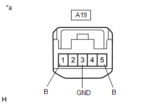
(b) Measure the voltage and resistance on the wire harness side connector according to the value(s) in the table below.
Standard Voltage:
| Tester Connection | Condition | Specified Condition |
|---|---|---|
| A1-1 (B) - A1-3 (GND) | Always | 11 to 14 V |
| A1-5 (B) - A1-3 (GND) | Always | 11 to 14 V |
Standard Resistance:
| Tester Connection | Condition | Specified Condition |
|---|---|---|
| A1-3 (GND) - Body ground | Always | Below 1 Ω |
If the result is not as specified, repair or replace the wire harness or connector.
(c) Reconnect the stop light switch assembly connector.
| (d) w/o Dynamic Radar Cruise Control System: Measure the voltage according to the value(s) in the table below. Standard Voltage:
If the result is not as specified, replace the stop light switch assembly. |
|
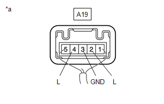
| (e) w/ Dynamic Radar Cruise Control System: Measure the voltage according to the value(s) in the table below. Standard Voltage:
If the result is not as specified, replace the stop light switch assembly. |
|
READ NEXT:
 Removal
REMOVAL PROCEDURE 1. REMOVE DOOR SCUFF PLATE ASSEMBLY LH Click here 2. REMOVE COWL SIDE TRIM BOARD LH Click here 3. REMOVE NO. 1 INSTRUMENT PANEL UNDER COVER SUB-ASSEMBLY Click here 4. R
Installation
INSTALLATION PROCEDURE 1. INSTALL STOP LIGHT SWITCH ASSEMBLY (a) Turn the stop light switch assembly in the clockwise direction until it reaches the standard shaft protrusion amount and temporarily
SEE MORE:
Over Current Detected in Driver Side Camera (C1687)
DESCRIPTION This DTC is stored if the parking assist ECU judges as a result of its self check that a synchronization problem is occurring in the image signal sent from the driver side television camera assembly to the parking assist ECU. DTC No. Detection Item DTC Detection Condition Troubl
On-vehicle Inspection
ON-VEHICLE INSPECTION PROCEDURE 1. INSPECT ENGINE COOLANT Click here 2. INSPECT ENGINE OIL Click here 3. INSPECT AUXILIARY BATTERY Click here 4. INSPECT AIR CLEANER FILTER ELEMENT SUB-ASSEMBLY (a) Remove the air cleaner cap sub-assembly. (b) Remove the air cleaner filter element sub-assembly.
