Lexus NX: On-vehicle Inspection
ON-VEHICLE INSPECTION
PROCEDURE
1. INSPECT WINDSHIELD WIPER MOTOR ASSEMBLY
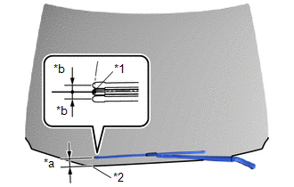
(a) for LH Side:
| (1) Check the stop (park) position. |
|
(2) Operate the windshield wiper motor assembly.
(3) Stop the windshield wiper motor assembly operation.
(4) Check the automatic stop (park) position.
HINT:
After the front wiper motor is stopped, check the automatic stop position after lifting the wiper blade 2 times.
OK:
The front wiper stops at the position shown in the illustration.
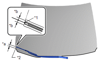
(b) for RH Side:
| (1) Check the stop (park) position. |
|
(2) Operate the windshield wiper motor assembly.
(3) Stop the windshield wiper motor assembly operation.
(4) Check the automatic stop (park) position.
HINT:
After the front wiper motor is stopped, check the automatic stop position after lifting the wiper blade 2 times.
OK:
The front wiper stops at the position shown in the illustration.
READ NEXT:
 Inspection
INSPECTION CAUTION / NOTICE / HINT CAUTION: Make sure that fingers or articles of clothing do not get caught in moving parts when performing this test. PROCEDURE 1. INSPECT WINDSHIELD WIPER MOTOR ASSE
Removal
REMOVAL PROCEDURE 1. REMOVE FRONT WIPER ARM HEAD CAP (a) Using a screwdriver, detach the 3 claws and remove the front wiper arm head cap. HINT:
Tape the screwdriver tip before use.
Use the sam
Installation
INSTALLATION PROCEDURE 1. INSTALL WINDSHIELD WIPER MOTOR ASSEMBLY (a) Install the windshield wiper motor assembly to the windshield wiper link assembly with the 3 bolts. Torque: 5.4 N·m {55 kgf·cm,
SEE MORE:
Open Circuit in Power Source Circuit (C13A0,C13A5,C13B0)
DESCRIPTION DTC No. Detection Item DTC Detection Condition Trouble Area Memory Note C13A0 Open Circuit in Power Source Circuit Both of following conditions are met:
Power switch on (IG) or electric parking brake switch (integration control and panel assembly) pulled to lock s
Fail-safe Chart
FAIL-SAFE CHART FAIL-SAFE FUNCTION (a) When a malfunction occurs in the pre-collision system, a message will be displayed on the multi-information display and the pre-collision system will be disabled depending on the malfunction. Warning Message Cause DTC/RoB Conditions to Return to Normal
