- Power switch off
- High mounted stop light off
- Luggage compartment room light off
- Window defogger off
Lexus NX: On-vehicle Inspection
Lexus NX Service Manual / Audio & Visual & Telematics / Audio / Video / Noise Filter / On-vehicle Inspection
ON-VEHICLE INSPECTION
PROCEDURE
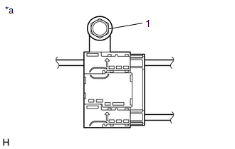
1. INSPECT RADIO SETTING CONDENSER
(a) With the radio setting condenser installed, check that there is no looseness or other abnormalities.
| (b) Measure the resistance of the radio setting condenser according to the value(s) in the table below. Standard Resistance:
|
|
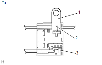
(c) Remove the bolt.
(d) Disengage the clamp and disconnect the radio setting condenser with wire harness from the vehicle body.
| (e) Measure the resistance and voltage of the radio setting condenser according to the value(s) in the table below. Standard Resistance:
Standard Voltage:
|
|
READ NEXT:
 Removal
REMOVAL PROCEDURE 1. REMOVE REAR SEAT ASSEMBLY (for Manual Seat) Click here 2. REMOVE REAR SEAT ASSEMBLY (for Power Seat) Click here 3. REMOVE TONNEAU COVER ASSEMBLY Click here 4. REMOVE DE
Installation
INSTALLATION PROCEDURE 1. INSTALL RADIO SETTING CONDENSER (a) Attach the claw to install a new terminal cover to the wire harness. NOTICE:
Make sure to hold the crimping side of the terminal w
SEE MORE:
Diagnostic Trouble Code Chart
DIAGNOSTIC TROUBLE CODE CHART Wireless Door Lock Control System DTC No. Detection Item Link B1242 Wireless Door Lock Tuner Circuit Malfunction
Installation
INSTALLATION PROCEDURE 1. INSTALL BACK DOOR OPENER SWITCH ASSEMBLY (a) Connect the connector. (b) Install the back door opener switch assembly. 2. INSTALL BACK DOOR OUTSIDE GARNISH SUB-ASSEMBLY Click here 3. INSTALL BACK DOOR TRIM BOARD ASSEMBLY Click here 4. INSTALL BACK DOOR LOCK COVER (w/ P
© 2016-2024 Copyright www.lexunx.com
