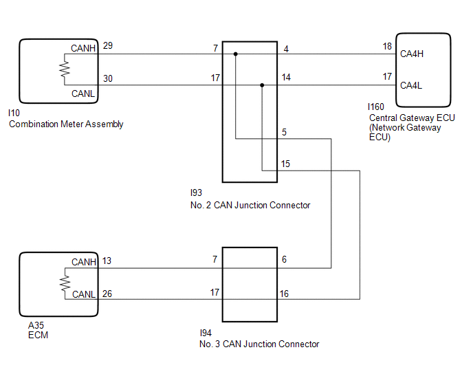
- CAN main bus wire or connector
- Central gateway ECU (network gateway ECU) branch wire
- ECM
- Combination meter assembly
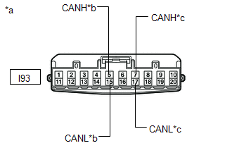
- No. 2 CAN junction connector
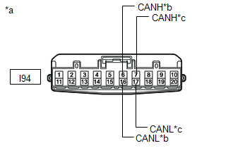
- No. 3 CAN junction connector
Lexus NX: Open in Bus 2 Main Bus Line
Lexus NX Service Manual / Power Source & Network / Networking / Can Communication System / Open in Bus 2 Main Bus Line
DESCRIPTION
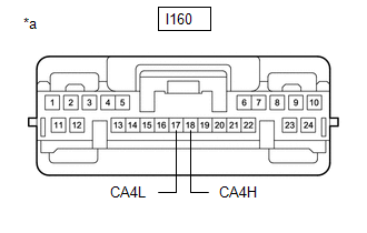
There may be an open circuit in one of the CAN main bus wire and/or a central gateway ECU (network gateway ECU) branch wire when the resistance between terminals 18 (CA4H) and 17 (CA4L) of the central gateway ECU (network gateway ECU) is 70 Ω or higher.
| Symptom | Trouble Area |
|---|---|
| Resistance between terminals 18 (CA4H) and 17 (CA4L) of central gateway ECU (network gateway ECU) is 70 Ω or higher. | |
This malfunction is not related to the lines of a CAN branch except the central gateway ECU (network gateway ECU) branch wire or to ECUs or sensors connected to a CAN branch.
WIRING DIAGRAM
CAUTION / NOTICE / HINT
CAUTION:
When performing the confirmation driving pattern, obey all speed limits and traffic laws.
NOTICE:
- Inspect the fuses for circuits related to this system before performing the following procedure.
- Before measuring the resistance of the CAN bus, turn the power switch off and leave the vehicle for 1 minute or more without operating the key or any switches, or opening or closing the doors. After that, disconnect the cable from the negative (-) auxiliary battery terminal and leave the vehicle for 1 minute or more before measuring the resistance.
-
After turning the power switch off, waiting time may be required before disconnecting the cable from the negative (-) auxiliary battery terminal.
Click here
.gif)
-
When disconnecting and reconnecting the auxiliary battery.
Click here
HINT:
When disconnecting and reconnecting the auxiliary battery, there is an automatic learning function that completes learning when the respective system is used.
Click here
-
Some parts must be initialized and set when replacing or removing and installing parts.
Click here
-
Because the order of diagnosis is important to allow correct diagnosis, make sure to begin troubleshooting using How to Proceed with Troubleshooting when CAN communication system related DTCs are output.
Click here
-
After performing repairs, perform the DTC check procedure and confirm that the DTCs are not output again.
DTC check procedure: Turn the power switch on (IG) and wait for 1 minute or more. Then operate the suspected malfunctioning system and drive the vehicle at 60 km/h (37 mph) or more for 5 minutes or more.
-
After the repair, perform the CAN bus check and check that all the ECUs and sensors connected to the CAN communication system are displayed as normal.
Click here
- When replacing the combination meter assembly, always replace it with a new one. If a combination meter assembly which was installed to another vehicle is used, the information stored in it will not match the information from the vehicle and a DTC may be stored
HINT:
- Operating the power switch, any switches or any doors triggers related ECU and sensor communication with the CAN, which causes resistance variation.
- Even after DTCs are cleared, if a DTC is stored again after driving the vehicle for a while, the malfunction may be occurring due to vibration of the vehicle. In such a case, wiggling the ECUs or wire harness while performing the inspection below may help determine the cause of the malfunction.
PROCEDURE
| 1. | CHECK FOR OPEN IN CAN BUS WIRE (CENTRAL GATEWAY ECU [NETWORK GATEWAY ECU] - NO. 2 CAN JUNCTION CONNECTOR) |
(a) Disconnect the cable from the negative (-) auxiliary battery terminal.
| (b) Disconnect the central gateway ECU (network gateway ECU) connector. |
|
(c) Measure the resistance according to the value(s) in the table below.
Standard Resistance:
| Tester Connection | Condition | Specified Condition |
|---|---|---|
| I160-18 (CA4H) - I160-17 (CA4L) | Cable disconnected from negative (-) auxiliary battery terminal | 108 to 132 Ω |
| NG | .gif) | REPAIR OR REPLACE CAN BRANCH WIRE OR CONNECTOR (CENTRAL GATEWAY ECU [NETWORK GATEWAY ECU] - NO. 2 CAN JUNCTION CONNECTOR) |
|
.gif)
| 2. | CONNECT CONNECTOR |
(a) Connect the I160 central gateway ECU (network gateway ECU) connector.
|
| 3. | CHECK FOR OPEN IN CAN BUS WIRE (NO. 2 CAN JUNCTION CONNECTOR) |
| (a) Disconnect the No. 2 CAN junction connector. |
|
(b) Measure the resistance according to the value(s) in the table below.
Standard Resistance:
| Tester Connection | Condition | Specified Condition | Connected to |
|---|---|---|---|
| I93-5 (CANH) - I93-15 (CANL) | Cable disconnected from negative (-) auxiliary battery terminal | 108 to 132 Ω | No. 3 CAN junction connector |
| I93-7 (CANH) - I93-17 (CANL) | Cable disconnected from negative (-) auxiliary battery terminal | 108 to 132 Ω | Combination meter assembly |
| Result | Proceed to |
|---|---|
| OK | A |
| NG (Combination meter assembly CAN main wire) | B |
| NG (No. 3 CAN junction connector CAN main wire) | C |
| A | | REPLACE NO. 2 CAN JUNCTION CONNECTOR |
| C | | GO TO STEP 6 |
|
| 4. | CONNECT CONNECTOR |
(a) Connect the I93 No. 2 CAN junction connector.
|
| 5. | CHECK FOR OPEN IN CAN BUS WIRE (COMBINATION METER ASSEMBLY - NO. 2 CAN JUNCTION CONNECTOR) |
| (a) Disconnect the combination meter assembly connector. |
|
.png)
(b) Measure the resistance according to the value(s) in the table below.
Standard Resistance:
| Tester Connection | Condition | Specified Condition |
|---|---|---|
| I10-29 (CANH) - I10-30 (CANL) | Cable disconnected from negative (-) auxiliary battery terminal | 108 to 132 Ω |
| OK | | REPLACE COMBINATION METER ASSEMBLY |
| NG | | REPAIR OR REPLACE CAN MAIN WIRE OR CONNECTOR (COMBINATION METER ASSEMBLY - NO. 2 CAN JUNCTION CONNECTOR) |
| 6. | CONNECT CONNECTOR |
(a) Connect the I93 No. 2 CAN junction connector.
|
| 7. | CHECK FOR OPEN IN CAN BUS WIRE (NO. 3 CAN JUNCTION CONNECTOR) |
| (a) Disconnect the No. 3 CAN junction connector. |
|
(b) Measure the resistance according to the value(s) in the table below.
Standard Resistance:
| Tester Connection | Condition | Specified Condition | Connected to |
|---|---|---|---|
| I94-6 (CANH) - I94-16 (CANL) | Cable disconnected from negative (-) auxiliary battery terminal | 108 to 132 Ω | No. 2 CAN junction connector |
| I94-7 (CANH) - I94-17 (CANL) | Cable disconnected from negative (-) auxiliary battery terminal | 108 to 132 Ω | ECM |
| Result | Proceed to |
|---|---|
| OK | A |
| NG (ECM CAN main wire) | B |
| NG (No. 2 CAN junction connector main wire) | C |
| A | | REPLACE NO. 3 CAN JUNCTION CONNECTOR |
| C | | REPAIR OR REPLACE CAN MAIN WIRE OR CONNECTOR (NO. 3 CAN JUNCTION CONNECTOR - NO. 2 CAN JUNCTION CONNECTOR) |
|
| 8. | CONNECT CONNECTOR |
(a) Connect the I94 No. 3 CAN junction connector.
|
| 9. | CHECK FOR OPEN IN CAN BUS WIRE (ECM - NO. 3 CAN JUNCTION CONNECTOR) |
| (a) Disconnect the ECM connector. |
|
(b) Measure the resistance according to the value(s) in the table below.
Standard Resistance:
| Tester Connection | Condition | Specified Condition |
|---|---|---|
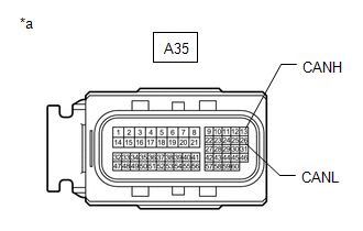
| A35-13 (CANH) - A35-26 (CANL) | Cable disconnected from negative (-) auxiliary battery terminal | 108 to 132 Ω |
| OK | | REPLACE ECM |
| NG | | REPAIR OR REPLACE CAN MAIN WIRE OR CONNECTOR (ECM - NO. 3 CAN JUNCTION CONNECTOR) |
READ NEXT:
 Check Bus 2 Lines for Short Circuit
DESCRIPTION There may be a short circuit between the CAN main bus wire and/or CAN branch wire when the resistance between terminals 18 (CA4H) and 17 (CA4L) of the central gateway ECU (network gateway
Check Bus 2 Line for Short to +B
DESCRIPTION There may be a short circuit between one of the CAN bus wire and +B when there is no resistance between terminal 18 (CA4H) of the central gateway ECU (network gateway ECU) and terminal 16
Check Bus 2 Line for Short to GND
DESCRIPTION There may be a short circuit between one of the CAN bus wire and GND when there is no resistance between terminal 18 (CA4H) of the central gateway ECU (network gateway ECU) and terminal 4
SEE MORE:
Customize Parameters
CUSTOMIZE PARAMETERS CUSTOMIZE LIGHTING SYSTEM (EXT) NOTICE:
When the customer requests a change in a function, first make sure that the function can be customized.
Record the current settings before customizing.
HINT: The following items can be customized. (a) Customizing with the Techstrea
Short in Motor Circuit (C1521-C1524,C1528,C1531-C1555)
DESCRIPTION The power steering ECU assembly detects steering force using the signal received from the steering torque sensor, and also monitors the motor circuit for errors. DTC No. Detection Item DTC Detection Condition Trouble Area Warning Indicate Return-to-normal Condition Note
© 2016-2024 Copyright www.lexunx.com
