Lexus NX: Parts Location
PARTS LOCATION
ILLUSTRATION
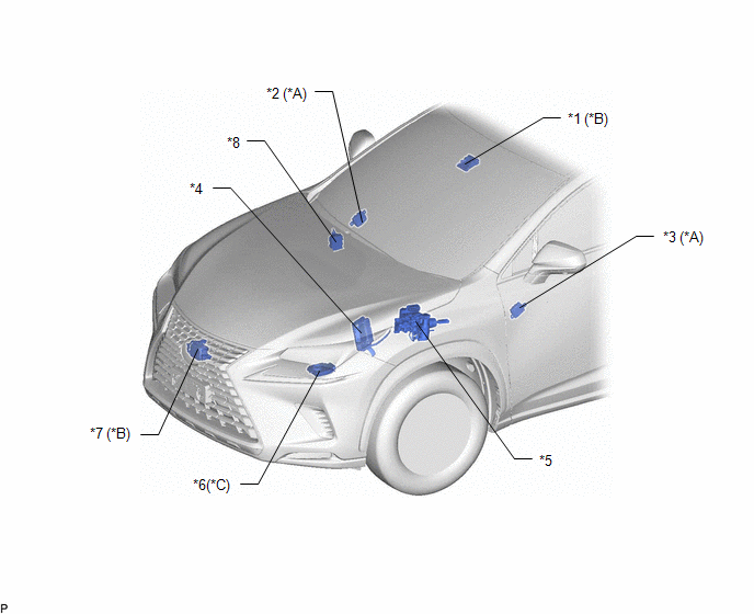
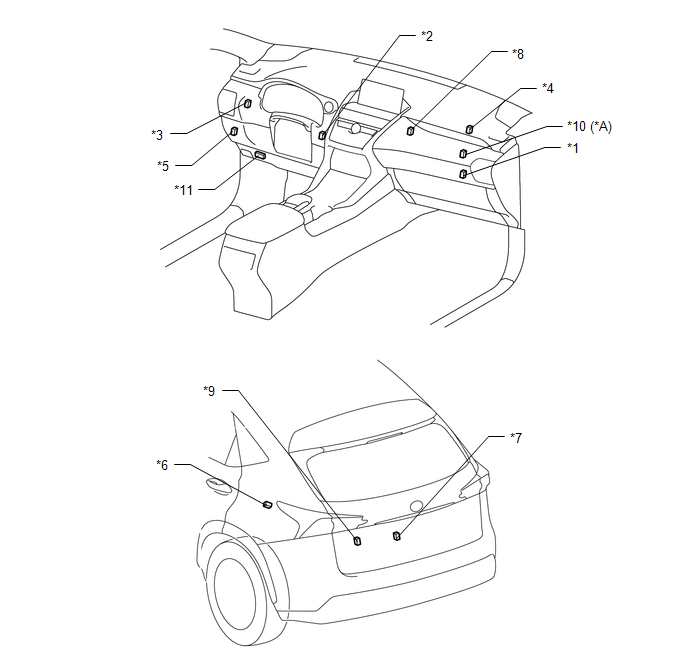
| *A | w/ Memory | *B | w/ Pre-collision System |
| *C | for Triple Beam Headlight | - | - |
| *1 | FORWARD RECOGNITION CAMERA | *2 | OUTER MIRROR CONTROL ECU ASSEMBLY RH |
| *3 | OUTER MIRROR CONTROL ECU ASSEMBLY LH | *4 | ECM |
| *5 | BRAKE BOOSTER WITH MASTER CYLINDER ASSEMBLY (SKID CONTROL ECU) | *6 | HEADLIGHT ECU SUB-ASSEMBLY LH |
| *7 | MILLIMETER WAVE RADAR SENSOR ASSEMBLY | *8 | VEHICLE APPROACHING SPEAKER CONTROLLER |
ILLUSTRATION
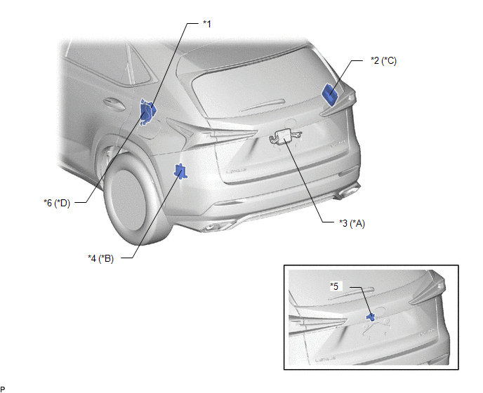
| *A | w/ Power Back Door System | *B | w/ Blind Spot Monitor System |
| *C | w/ Panoramic View Monitor System | *D | w/ Adaptive Variable Suspension System |
| *1 | PARKING BRAKE ECU ASSEMBLY | *2 | PARKING ASSIST ECU |
| *3 | MULTIPLEX NETWORK DOOR ECU | *4 | BLIND SPOT MONITOR SENSOR LH |
| *5 | REAR TELEVISION CAMERA ASSEMBLY | *6 | ABSORBER CONTROL ECU |
ILLUSTRATION
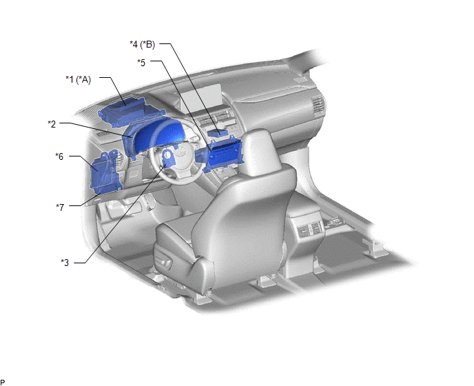
| *A | w/ Headup Display | *B | w/ ASC System |
| *1 | METER MIRROR SUB-ASSEMBLY | *2 | COMBINATION METER ASSEMBLY |
| *3 | STEERING SENSOR | *4 | STEREO COMPONENT EQUALIZER ASSEMBLY |
| *5 | RADIO RECEIVER ASSEMBLY | *6 | MAIN BODY ECU (MULTIPLEX NETWORK BODY ECU) |
| *7 | INSTRUMENT PANEL JUNCTION BLOCK ASSEMBLY | - | - |
ILLUSTRATION
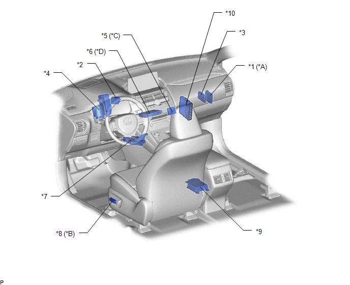
| *A | w/ Intuitive Parking Assist System | *B | w/ Memory |
| *C | for Power Tilt and Power Telescopic Steering Column | *D | w/ Telematics Transceiver |
| *1 | CLEARANCE WARNING ECU ASSEMBLY | *2 | CERTIFICATION ECU (SMART KEY ECU ASSEMBLY) |
| *3 | CENTRAL GATEWAY ECU (NETWORK GATEWAY ECU) | *4 | POWER STEERING ECU ASSEMBLY |
| *5 | MULTIPLEX TILT AND TELESCOPIC ECU | *6 | DCM (TELEMATICS TRANSCEIVER) |
| *7 | AIR CONDITIONING AMPLIFIER ASSEMBLY | *8 | FRONT POWER SEAT SWITCH (FOR DRIVER SIDE) |
| *9 | AIRBAG ECU ASSEMBLY | *10 | HYBRID VEHICLE CONTROL ECU |
ILLUSTRATION
| *A | w/ Bus Buffer ECU | - | - |
| *1 | NO. 2 CAN JUNCTION CONNECTOR | *2 | NO. 3 CAN JUNCTION CONNECTOR |
| *3 | NO. 4 CAN JUNCTION CONNECTOR | *4 | NO. 5 CAN JUNCTION CONNECTOR |
| *5 | NO. 6 CAN JUNCTION CONNECTOR | *6 | NO. 7 CAN JUNCTION CONNECTOR |
| *7 | NO. 8 CAN JUNCTION CONNECTOR | *8 | NO. 10 CAN JUNCTION CONNECTOR |
| *9 | NO. 2 CAN JUNCTION TERMINAL | *10 | BUS BUFFER ECU |
| *11 | DLC3 | - | - |
READ NEXT:
 System Diagram
SYSTEM DIAGRAM SYSTEM DIAGRAM (a) The CAN communication system is composed of 5 buses. CAN Main Bus Line Terminating Resistor CAN Branch Line * Gateway Function Equipped ECU
System Description
SYSTEM DESCRIPTION BRIEF DESCRIPTION (a) The Controller Area Network (CAN) is a serial data communication system for real time application. It is a vehicle multiplex communication system which has a h
How To Proceed With Troubleshooting
CAUTION / NOTICE / HINT PRECAUTIONS WHEN TROUBLESHOOTING NOTICE:
Because the order of diagnosis is important to allow correct diagnosis, make sure to begin troubleshooting using How to Proceed with
SEE MORE:
Problem Symptoms Table
PROBLEM SYMPTOMS TABLE HINT:
Inspect the fuses and relays related to this system before inspecting the suspected areas below.
If the problem only occurs in certain locations or at certain times of day, check for wave interference.
If optional components are installed, check for wave interfere
Problem Symptoms Table
PROBLEM SYMPTOMS TABLE HINT:
Use the table below to help determine the cause of problem symptoms. If multiple suspected areas are listed, the potential causes of the symptoms are listed in order of probability in the "Suspected Area" column of the table. Check each symptom by checking the suspect
