Lexus NX: Parts Location
PARTS LOCATION
ILLUSTRATION
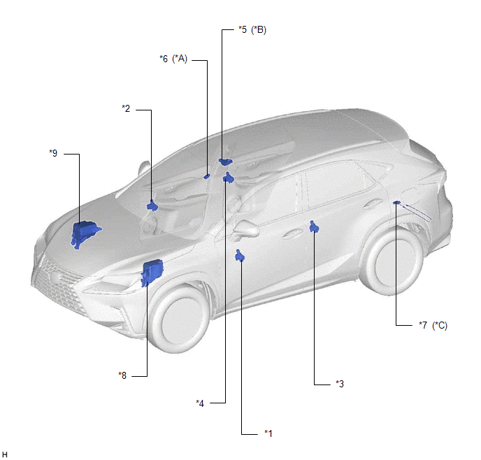
| *A | w/ Rain Sensor | *B | w/ Sliding Roof System |
| *C | w/ Hands Free Power Back Door | - | - |
| *1 | FRONT POWER WINDOW REGULATOR MOTOR ASSEMBLY LH | *2 | FRONT POWER WINDOW REGULATOR MOTOR ASSEMBLY RH |
| *3 | REAR POWER WINDOW REGULATOR MOTOR ASSEMBLY LH | *4 | REAR POWER WINDOW REGULATOR MOTOR ASSEMBLY RH |
| *5 | SLIDING ROOF DRIVE GEAR SUB-ASSEMBLY | *6 | RAIN SENSOR |
| *7 | KICK DOOR CONTROL SENSOR | *8 | ENGINE ROOM RELAY BLOCK - STRG LOCK FUSE |
| *9 | NO. 2 ENGINE ROOM RELAY BLOCK - ECU-B NO.1 FUSE - ECU-B NO.2 FUSE - IMMOBI FUSE - DOOR R/R FUSE | - | - |
ILLUSTRATION
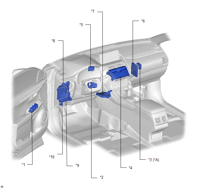
| *A | w/ Rain Sensor | - | - |
| *1 | MULTIPLEX NETWORK MASTER SWITCH ASSEMBLY | *2 | STEERING LOCK ACTUATOR ASSEMBLY |
| *3 | WINDSHIELD WIPER RELAY ASSEMBLY | *4 | AIR CONDITIONING CONTROL ASSEMBLY |
| *5 | ID CODE BOX (IMMOBILISER CODE ECU) | *6 | CERTIFICATION ECU (SMART KEY ECU ASSEMBLY) |
| *7 | AIR CONDITIONING AMPLIFIER ASSEMBLY | *8 | MAIN BODY ECU (MULTIPLEX NETWORK BODY ECU) |
| *9 | INSTRUMENT PANEL JUNCTION BLOCK ASSEMBLY - DOOR F/L FUSE - DOOR F/R FUSE - DOOR R/L FUSE - ECU-IG NO.2 FUSE - WIPER FUSE - ACC FUSE - IG2 NO.3 FUSE - S/ROOF FUSE (w/ Sliding Roof System) | *10 | DLC3 |
READ NEXT:
 System Diagram
SYSTEM DIAGRAM DOOR BUS LINES CERTIFICATION BUS LINES AIR CONDITIONING BUS LINES WINDSHIELD WIPER BUS LINE (w/ Rain Sensor)
System Description
SYSTEM DESCRIPTION LIN COMMUNICATION SYSTEM DESCRIPTION The LIN communication system is used for communication between the components in the tables below. If communication cannot be performed through
How To Proceed With Troubleshooting
CAUTION / NOTICE / HINT HINT:
Use these procedures to troubleshoot the LIN communication system.
*: Use the Techstream.
PROCEDURE 1. VEHICLE BROUGHT TO WORKSHOP
NEXT
SEE MORE:
Inspection
INSPECTION CAUTION / NOTICE / HINT NOTICE:
When using a vise, place aluminum plates between the part and vise.
When using a vise, do not overtighten it.
PROCEDURE 1. INSPECT FRONT DRIVE SHAFT ASSEMBLY (a) Check that there is no excessive play in the radial direction of the inboard joint a
Diagnosis System
DIAGNOSIS SYSTEM DESCRIPTION (a) When troubleshooting a vehicle with the diagnostic system, the only difference from the usual troubleshooting procedure is connecting the Techstream to the vehicle and reading various data output from the multiplex tilt and telescopic ECU. The multiplex tilt and tele
