Lexus NX: Parts Location
PARTS LOCATION
ILLUSTRATION
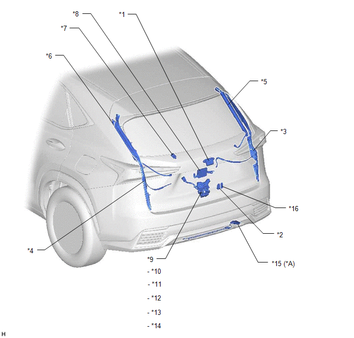
| *A | w/ Hands Free Power Back Door | - | - |
| *1 | BACK DOOR OPENER SWITCH ASSEMBLY | *2 | BACK DOOR CONTROL SWITCH |
| *3 | POWER BACK DOOR SENSOR ASSEMBLY RH | *4 | POWER BACK DOOR SENSOR ASSEMBLY LH |
| *5 | POWER BACK DOOR UNIT ASSEMBLY SET RH | *6 | POWER BACK DOOR UNIT ASSEMBLY SET LH |
| *7 | POWER BACK DOOR WARNING BUZZER | *8 | MULTIPLEX NETWORK DOOR ECU |
| *9 | BACK DOOR LOCK ASSEMBLY | *10 | BACK DOOR LOCK MOTOR |
| *11 | BACK DOOR COURTESY SWITCH | *12 | LATCH SWITCH |
| *13 | INITIAL SWITCH | *14 | PAWL SWITCH |
| *15 | KICK DOOR CONTROL SENSOR | *16 | DOOR CONTROL SWITCH |
ILLUSTRATION
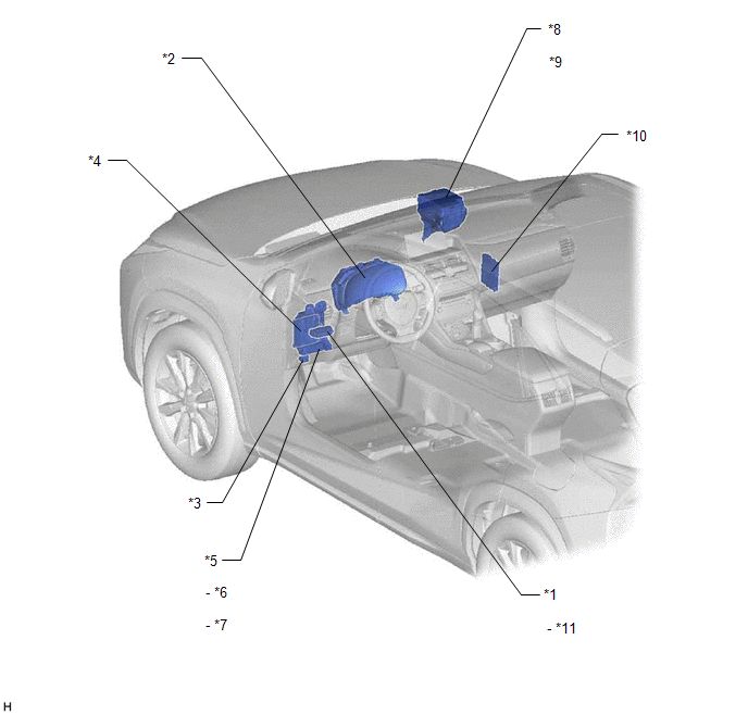
| *1 | COMBINATION SWITCH ASSEMBLY | *2 | COMBINATION METER ASSEMBLY |
| *3 | DLC3 | *4 | MAIN BODY ECU (MULTIPLEX NETWORK BODY ECU) |
| *5 | INSTRUMENT PANEL JUNCTION BLOCK ASSEMBLY | *6 | PBD FUSE |
| *7 | ECU-IG NO.1 FUSE | *8 | ENGINE ROOM RELAY BLOCK |
| *9 | ECU-B NO.1 FUSE | *10 | CERTIFICATION ECU (SMART KEY ECU ASSEMBLY) |
| *11 | POWER BACK DOOR SWITCH | - | - |
READ NEXT:
 System Diagram
SYSTEM DIAGRAM Communication Table Transmitting ECU Receiving ECU Signal Communication Method Main body ECU (multiplex network body ECU) Multiplex network door ECU
Combination s
System Description
SYSTEM DESCRIPTION POWER BACK DOOR SYSTEM DESCRIPTION (a) The power back door system controls the power back door by automatically opening and closing the power back door with a motor. (1) The power b
How To Proceed With Troubleshooting
CAUTION / NOTICE / HINT HINT:
The power back door system troubleshooting procedure is based on the premise that the smart access system with push-button start (for Entry Function) is operating norm
SEE MORE:
If your vehicle needs to be towed
If towing is necessary, we recommend
having your vehicle towed by
your Lexus dealer or commercial
towing service, using a wheel-lift
type truck or flatbed truck.
Use a safety chain system for all
towing, and abide by all state/provincial
and local laws.
If towing your vehicle with a whee
Short in D Squib Circuit (B1800-B1803)
DESCRIPTION The driver side squib circuit consists of the airbag ECU assembly, spiral cable sub-assembly and horn button assembly. The circuit instructs the SRS to deploy when deployment conditions are met. These DTCs are stored when a malfunction is detected in the driver side squib circuit. DTC
