Lexus NX: Parts Location
Lexus NX Service Manual / Vehicle Exterior / Lighting (ext) / Automatic High Beam System / Parts Location
PARTS LOCATION
ILLUSTRATION
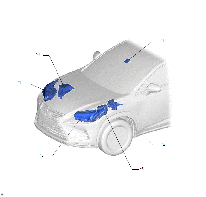
| *1 | FORWARD RECOGNITION CAMERA | *2 | BRAKE BOOSTER WITH MASTER CYLINDER ASSEMBLY (SKID CONTROL ECU) |
| *3 | HEADLIGHT ASSEMBLY LH | *4 | HEADLIGHT ASSEMBLY RH |
| *5 | ENGINE ROOM RELAY BLOCK - H-LP LH/DIMMER(HI) RELAY (for Single Beam Headlight) | *6 | NO. 2 ENGINE ROOM RELAY BLOCK - H-LP RH RELAY (for Triple Beam Headlight) |
ILLUSTRATION
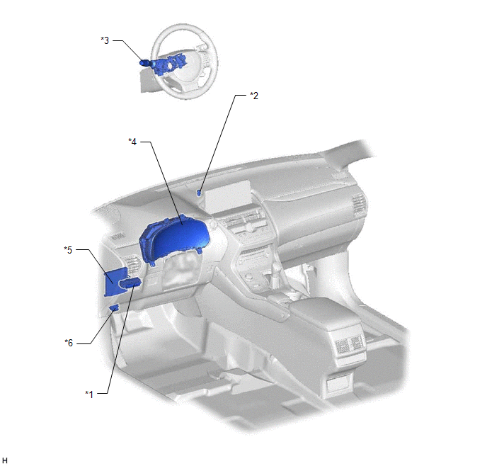
| *1 | COMBINATION SWITCH ASSEMBLY (AUTOMATIC HIGH BEAM MAIN SWITCH) | *2 | AUTOMATIC LIGHT CONTROL SENSOR |
| *3 | HEADLIGHT DIMMER SWITCH ASSEMBLY | *4 | COMBINATION METER ASSEMBLY |
| *5 | MAIN BODY ECU (MULTIPLEX NETWORK BODY ECU) | *6 | DLC3 |
READ NEXT:
 System Diagram
SYSTEM DIAGRAM
System Description
SYSTEM DESCRIPTION AUTOMATIC HIGH BEAM SYSTEM (a) General The automatic high beam system enhances the illumination of the area in front of the vehicle to improve visibility for the driver. It works by
How To Proceed With Troubleshooting
CAUTION / NOTICE / HINT HINT:
Use the following procedure to troubleshoot the automatic high beam system.
*: Use the Techstream.
PROCEDURE 1. VEHICLE BROUGHT TO WORKSHOP
NEXT
SEE MORE:
System Description
SYSTEM DESCRIPTION GENERAL (a) In the occupant classification system, the occupant detection ECU calculates the weight of the occupant based on signals from the occupant classification sensors. This system recognizes the occupant as a child if it detects a weight of less than 17 kg (37.4 lb) on the
Tilt Position Sensor or Tilt Motor Circuit Malfunction (B2610)
DESCRIPTION The tilt motor is operated by the power source voltage supplied from the multiplex tilt and telescopic ECU and tilts the steering column up and down. The tilt position sensor (Hall IC) in the tilt motor detects the tilt angle of the steering column and sends a signal to the multiplex til
© 2016-2024 Copyright www.lexunx.com
