- - AM2 FUSE
Lexus NX: Parts Location
Lexus NX Service Manual / Vehicle Interior / Door Lock / Wireless Door Lock Control System / Parts Location
PARTS LOCATION
ILLUSTRATION
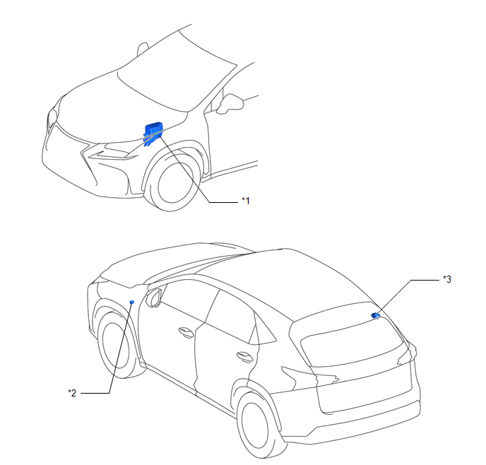
| *1 | ENGINE ROOM RELAY BLOCK | *2 | WIRELESS DOOR LOCK BUZZER |
| *3 | DOOR CONTROL RECEIVER | - | - |
ILLUSTRATION
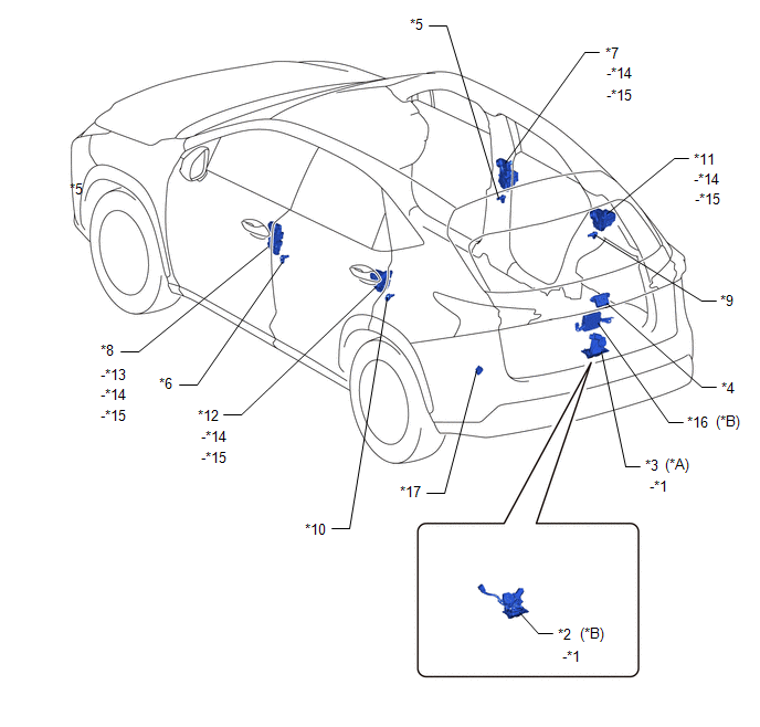
| *A | w/o Power Back Door System | *B | w/ Power Back Door System |
| *1 | BACK DOOR COURTESY LIGHT SWITCH ASSEMBLY | *2 | BACK DOOR LOCK ASSEMBLY |
| *3 | BACK DOOR LOCK ASSEMBLY | *4 | BACK DOOR OPENER SWITCH ASSEMBLY |
| *5 | FRONT DOOR COURTESY LIGHT SWITCH ASSEMBLY RH | *6 | FRONT DOOR COURTESY LIGHT SWITCH ASSEMBLY LH |
| *7 | FRONT DOOR LOCK ASSEMBLY RH | *8 | FRONT DOOR LOCK ASSEMBLY LH |
| *9 | REAR DOOR COURTESY LIGHT SWITCH ASSEMBLY RH | *10 | REAR DOOR COURTESY LIGHT SWITCH ASSEMBLY LH |
| *11 | REAR DOOR LOCK ASSEMBLY RH | *12 | REAR DOOR LOCK ASSEMBLY LH |
| *13 | DOOR KEY LOCK AND UNLOCK SWITCH | *14 | DOOR UNLOCK DETECTION SWITCH |
| *15 | DOOR LOCK MOTOR | *16 | MULTIPLEX NETWORK DOOR ECU |
| *17 | FUSE BLOCK ASSEMBLY
| - | - |
ILLUSTRATION
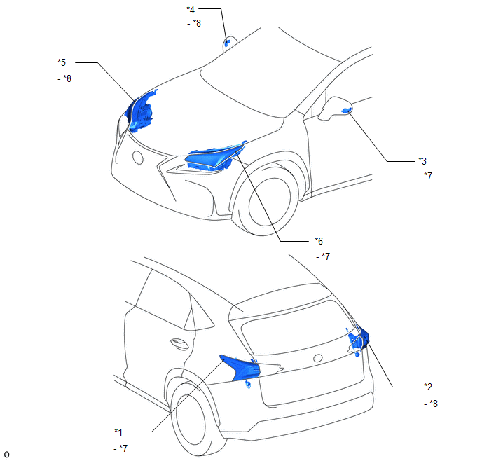
| *1 | REAR COMBINATION LIGHT ASSEMBLY LH | *2 | REAR COMBINATION LIGHT ASSEMBLY RH |
| *3 | SIDE TURN SIGNAL LIGHT ASSEMBLY LH | *4 | SIDE TURN SIGNAL LIGHT ASSEMBLY RH |
| *5 | HEADLIGHT ASSEMBLY RH | *6 | HEADLIGHT ASSEMBLY LH |
| *7 | TURN SIGNAL LIGHT LH | *8 | TURN SIGNAL LIGHT RH |
ILLUSTRATION
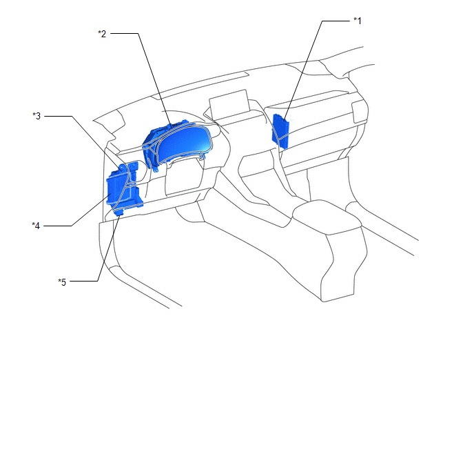
| *1 | CERTIFICATION ECU (SMART KEY ECU ASSEMBLY) | *2 | COMBINATION METER ASSEMBLY |
| *3 | INSTRUMENT PANEL JUNCTION BLOCK ASSEMBLY
| *4 | MAIN BODY ECU (MULTIPLEX NETWORK BODY ECU) |
| *5 | DLC3 | - | - |
READ NEXT:
 System Diagram
SYSTEM DIAGRAM Wireless Door Lock Control System
System Description
SYSTEM DESCRIPTION WIRELESS DOOR LOCK CONTROL SYSTEM The wireless door lock control system can be used to lock and unlock all doors from a distance. The system is controlled by an electrical key trans
How To Proceed With Troubleshooting
CAUTION / NOTICE / HINT HINT:
The wireless door lock control system troubleshooting procedure is based on the premise that the power door lock control system is operating properly. Check the power
SEE MORE:
Fuel Receiver Gauge Display Malfunction
DESCRIPTION OPERATION The combination meter assembly uses the fuel injection volume signal from the ECM, fuel sender gauge assembly to detect the amount of fuel remaining in the fuel tank assembly. Each gauge assembly has a variable resistor whose resistance changes according to the amount of fuel r
Installation
INSTALLATION PROCEDURE 1. INSTALL INNER REAR VIEW MIRROR ASSEMBLY (a) Slide the inner rear view mirror assembly in the direction indicated by the arrow shown in the illustration to install the inner rear view mirror assembly. *a Screw *b Connector (b) Using a T20 "TO
© 2016-2024 Copyright www.lexunx.com
