Lexus NX: Parts Location
Lexus NX Service Manual / Vehicle Interior / Meter / Gauge / Display / Headup Display System / Parts Location
PARTS LOCATION
ILLUSTRATION
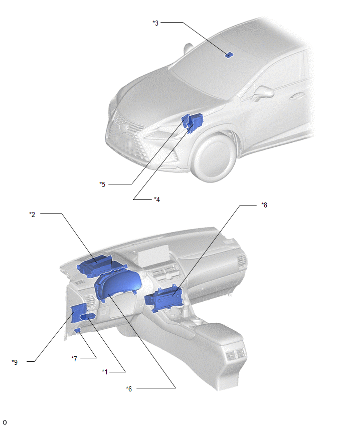
| *1 | HEADUP DISPLAY SWITCH ASSEMBLY | *2 | METER MIRROR SUB-ASSEMBLY |
| *3 | FORWARD RECOGNITION CAMERA | *4 | NO. 2 ENGINE ROOM RELAY BLOCK - ECU-B NO.1 FUSE |
| *5 | ECM | *6 | COMBINATION METER ASSEMBLY |
| *7 | DLC3 | *8 | RADIO RECEIVER ASSEMBLY |
| *9 | MAIN BODY ECU(MULTIPLEX NETWORK BODY ECU) | - | - |
READ NEXT:
 System Diagram
SYSTEM DIAGRAM
System Description
SYSTEM DESCRIPTION HEADUP DISPLAY SYSTEM DESCRIPTION HINT:
The meter mirror sub-assembly receives signals from the combination meter assembly via the CAN communication line. Information is displaye
Customize Parameters
CUSTOMIZE PARAMETERS CUSTOMIZE HEADUP DISPLAY SYSTEM (a) Customizing with the Techstream (1) Connect the Techstream to the DLC3. (2) Turn the power switch on (IG). (3) Turn the Techstream on. (4) Ente
SEE MORE:
Front Passenger Side Door Entry Lock and Unlock Functions do not Operate
DESCRIPTION If the entry lock and unlock functions do not operate for the front passenger door only, the request code may not be being transmitted from the front passenger door or the front door outside handle assembly (for front passenger door) (touch sensor) may be malfunctioning. If the entry fun
Open in One Side of Bus 5 Branch Line
DESCRIPTION When the CAN bus main lines are normal (no open, short to ground, short to +B or short between lines) and there is an ECU or sensor on the "Communication Bus Check" screen that is indicated as not communicating or whose connection status on the "Communication Bus Check" screen changes in
© 2016-2024 Copyright www.lexunx.com
