- - RR S-HTR RELAY (w/ Rear Seat Heater)
Lexus NX: Parts Location
PARTS LOCATION
ILLUSTRATION
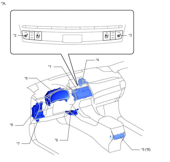
| *A | w/ Rear Seat Heater | - | - |
| *1 | AIR CONDITIONING CONTROL ASSEMBLY | *2 | SEAT HEATER SWITCH (for Driver Side) |
| *3 | SEAT HEATER SWITCH (for Front Passenger Side) | *4 | NO. 3 RELAY BLOCK |
| *5 | REFRESHING SEAT SWITCH | *6 | AIR CONDITIONING AMPLIFIER ASSEMBLY |
| *7 | DLC3 | *8 | INSTRUMENT PANEL JUNCTION BLOCK ASSEMBLY
|
| *9 | COMBINATION METER ASSEMBLY | - | - |
ILLUSTRATION
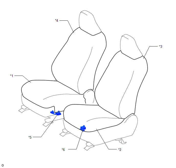
| *1 | SEPARATE TYPE FRONT SEAT CUSHION COVER RH | *2 | SEPARATE TYPE FRONT SEAT CUSHION COVER LH |
| *3 | SEPARATE TYPE FRONT SEATBACK COVER LH | *4 | SEPARATE TYPE FRONT SEATBACK COVER RH |
| *5 | SEAT HEATER CONTROL SUB-ASSEMBLY RH | *6 | SEAT HEATER CONTROL SUB-ASSEMBLY LH |
ILLUSTRATION
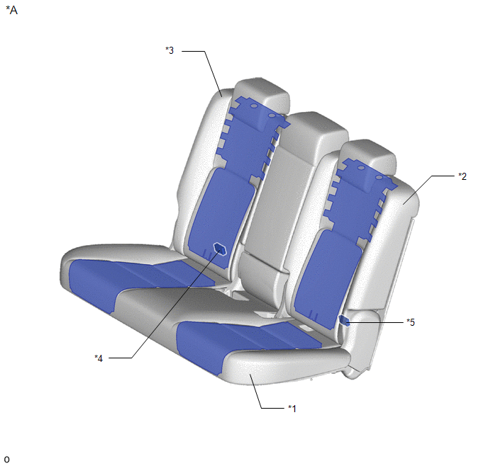
| *A | w/ Rear Seat Heater | - | - |
| *1 | BENCH TYPE REAR SEAT CUSHION COVER | *2 | SEPARATE TYPE REAR SEATBACK COVER LH |
| *3 | SEPARATE TYPE REAR SEATBACK COVER RH | *4 | SEAT HEATER CONTROL SUB-ASSEMBLY RH |
| *5 | SEAT HEATER CONTROL SUB-ASSEMBLY LH | - | - |
ILLUSTRATION
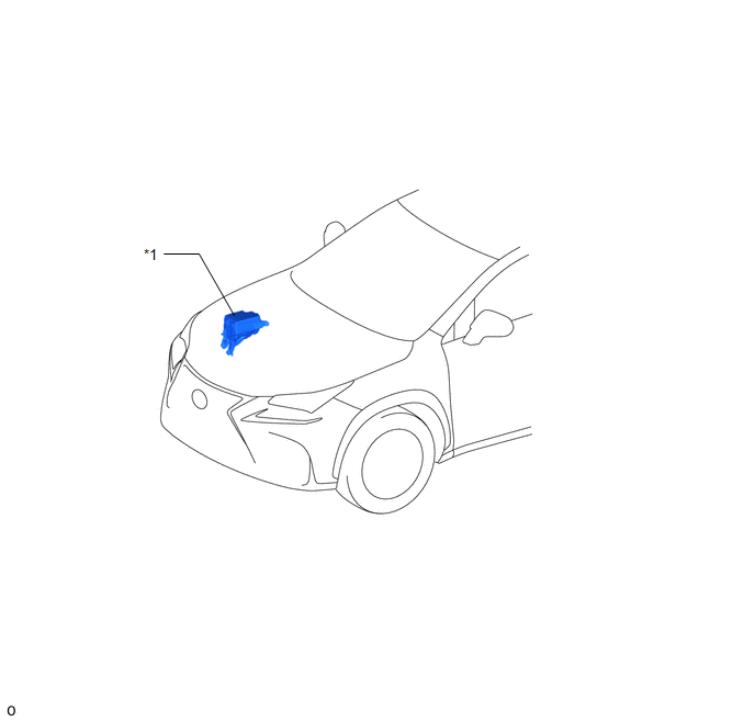
| *1 | NO. 2 ENGINE ROOM RELAY BLOCK
| - | - |
READ NEXT:
 System Diagram
SYSTEM DIAGRAM for Front: for Rear (w/ Rear Seat Heater):
System Description
SYSTEM DESCRIPTION FRONT SEAT HEATER (a) By operating the seat heater switch on the air conditioning control assembly, the temperature can be controlled within the range of 32 to 43°C (89 to 109°F).
How To Proceed With Troubleshooting
CAUTION / NOTICE / HINT HINT:
Use the following procedure to troubleshoot the seat heater system.
*: Use the Techstream.
PROCEDURE 1. VEHICLE BROUGHT TO WORKSHOP
NEXT
SEE MORE:
Fail-safe Chart
FAIL-SAFE CHART FAIL SAFE FUNCTION (a) The following chart shows the status of the controls when the system is normal and malfunctioning.
The passenger airbag ON/OFF indicator ("ON" and "OFF") comes on for approximately 4 seconds, and then goes off for approximately 2 seconds.
Approximately 6 s
Removal
REMOVAL CAUTION / NOTICE / HINT HINT:
Use the same procedure for the RH and LH sides.
The procedure listed below is for the LH side.
PROCEDURE 1. REMOVE ROOF RACK ASSEMBLY (w/ Roof Rack) Click here 2. REMOVE ROOF DRIP SIDE FINISH MOULDING LH (w/ Roof Rack) (a) Put protective tape around
© 2016-2024 Copyright www.lexunx.com
