Lexus NX: Parts Location
PARTS LOCATION
ILLUSTRATION
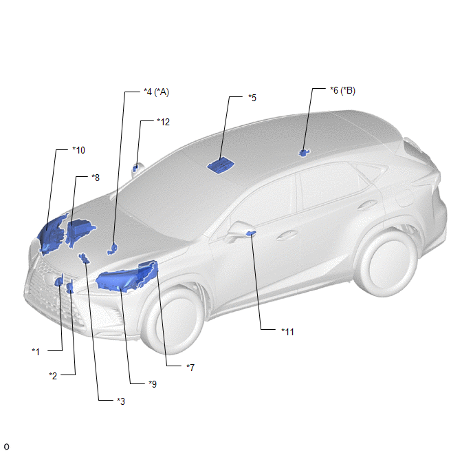
| *A | w/ Security Horn Assembly | *B | w/o Security Horn Assembly |
| *1 | HIGH PITCHED HORN ASSEMBLY | *2 | LOW PITCHED HORN ASSEMBLY |
| *3 | HOOD LOCK ASSEMBLY (ENGINE HOOD COURTESY SWITCH) | *4 | SECURITY HORN ASSEMBLY |
| *5 | MAP LIGHT ASSEMBLY | *6 | THEFT WARNING SIREN ASSEMBLY |
| *7 | NO. 1 ENGINE ROOM RELAY BLOCK AND JUNCTION BLOCK ASSEMBLY - AM2 FUSE - ECU-B NO.5 FUSE | *8 | NO. 2 ENGINE ROOM RELAY BLOCK AND JUNCTION BLOCK ASSEMBLY - ECU-B NO.1 FUSE - ECU-B NO.2 FUSE - HORN FUSE - HORN RELAY - SECURITY WARNING RELAY (w/ Security Horn Assembly) |
| *9 | HEADLIGHT ASSEMBLY LH | *10 | HEADLIGHT ASSEMBLY RH |
| *11 | SIDE TURN SIGNAL LIGHT ASSEMBLY LH | *12 | SIDE TURN SIGNAL LIGHT ASSEMBLY RH |
ILLUSTRATION
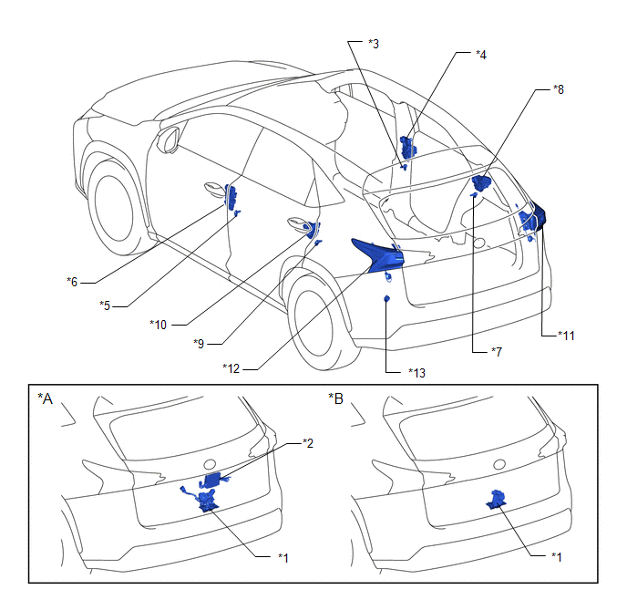
| *A | w/ Power Back Door System | *B | w/o Power Back Door System |
| *1 | BACK DOOR LOCK ASSEMBLY | *2 | MULTIPLEX NETWORK DOOR ECU |
| *3 | FRONT DOOR COURTESY LIGHT SWITCH ASSEMBLY RH | *4 | FRONT DOOR LOCK ASSEMBLY RH |
| *5 | FRONT DOOR COURTESY LIGHT SWITCH ASSEMBLY LH | *6 | FRONT DOOR LOCK ASSEMBLY LH |
| *7 | REAR DOOR COURTESY LIGHT SWITCH ASSEMBLY RH | *8 | REAR DOOR LOCK ASSEMBLY RH |
| *9 | REAR DOOR COURTESY LIGHT SWITCH ASSEMBLY LH | *10 | REAR DOOR LOCK ASSEMBLY LH |
| *11 | REAR COMBINATION LIGHT LENS AND BODY RH | *12 | REAR COMBINATION LIGHT LENS AND BODY LH |
| *13 | FUSE BLOCK ASSEMBLY - ECU-B NO.3 FUSE | - | - |
ILLUSTRATION
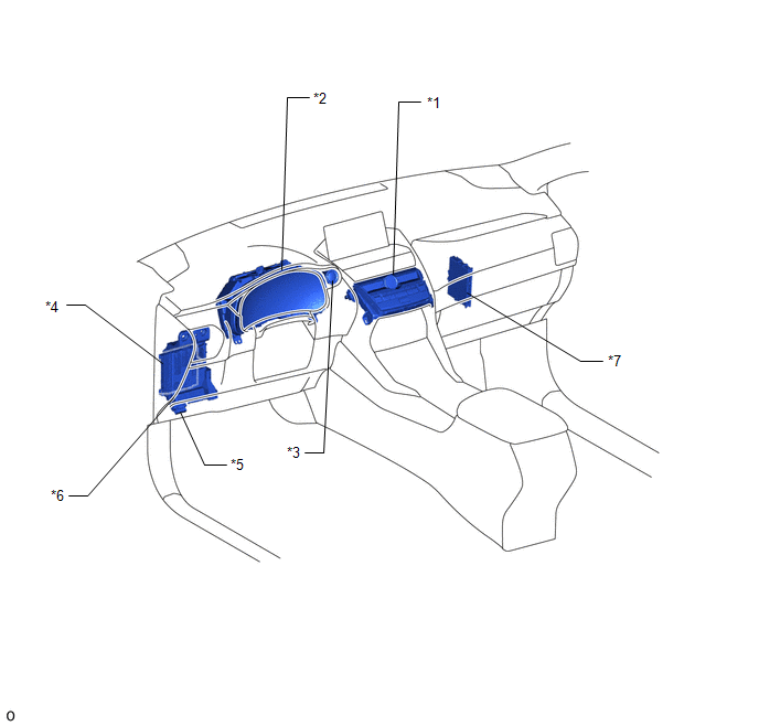
| *1 | AIR CONDITIONING CONTROL ASSEMBLY - SECURITY INDICATOR LIGHT | *2 | COMBINATION METER ASSEMBLY |
| *3 | POWER SWITCH | *4 | MAIN BODY ECU (MULTIPLEX NETWORK BODY ECU) |
| *5 | DLC3 | *6 | INSTRUMENT PANEL JUNCTION BLOCK ASSEMBLY - ACC FUSE - ECU-IG NO.2 FUSE |
| *7 | CERTIFICATION ECU (SMART KEY ECU ASSEMBLY) | - | - |
READ NEXT:
 System Description
SYSTEM DESCRIPTION
The theft deterrent system can be set/canceled by locking/unlocking the doors performing any of the following operation:
Entry lock/unlock operation
Wireless lock/unlock ope
How To Proceed With Troubleshooting
CAUTION / NOTICE / HINT HINT:
Use this procedure to troubleshoot the theft deterrent system.
*: Use the Techstream.
PROCEDURE 1. VEHICLE BROUGHT TO WORKSHOP
NEXT 2
Customize Parameters
CUSTOMIZE PARAMETERS INSTALL CUSTOMIZE THEFT DETERRENT SYSTEM HINT: The following items can be customized. NOTICE:
When the customer requests a change in a function, first make sure that the functi
SEE MORE:
Steering Angle Midpoint Initial Setting Incomplete (C1AEA)
DESCRIPTION When the clearance warning ECU assembly detects that the steering angle neutral point memorization is incomplete during self-diagnosis, C1AEA is stored. DTC No. Detection Item DTC Detection Condition Trouble Area C1AEA Steering Angle Midpoint Initial Setting Incomplete S
Removal
REMOVAL PROCEDURE 1. REMOVE NO. 3 DECK BOARD SUB-ASSEMBLY Click here 2. REMOVE REAR DECK FLOOR BOX Click here 3. REMOVE DECK FLOOR BOX LH Click here 4. PRECAUTION CAUTION: Be sure to read Precaution thoroughly before servicing. Click here NOTICE: After the power switch is turned off, there m
