Lexus NX: Parts Location
PARTS LOCATION
ILLUSTRATION
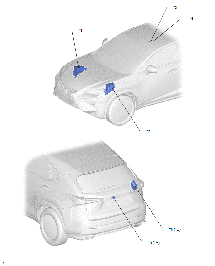
| *A | w/ Parking Assist Monitor System | *B | w/ Panoramic View Monitor System |
| *1 | NO. 2 ENGINE ROOM RELAY BLOCK - DCM FUSE (w/ Manual [SOS] Switch) - ECU-B NO.1 FUSE - ECU-B NO.5 FUSE | *2 | NO. 1 ENGINE ROOM RELAY BLOCK - AMP FUSE - RADIO FUSE - METER NO.1 FUSE |
| *3 | TELEPHONE MICROPHONE ASSEMBLY | *4 | NO. 1 MICROPHONE CASE |
| *5 | TELEVISION CAMERA ASSEMBLY | *6 | PARKING ASSIST ECU |
ILLUSTRATION
.png)
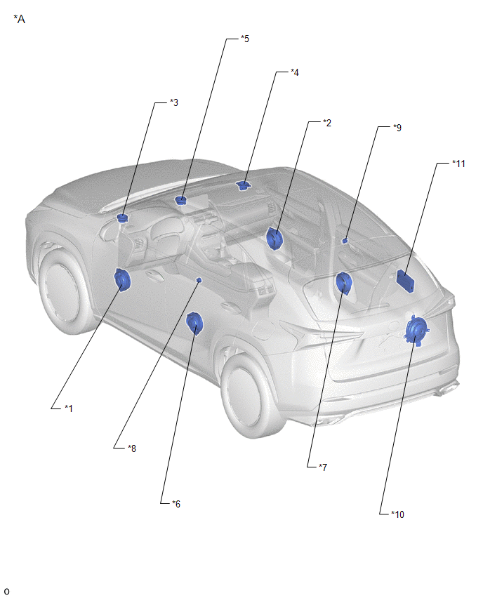
| *A | w/ SXM System or Manual (SOS) Switch | - | - |
| *1 | NAVIGATION ANTENNA ASSEMBLY | *2 | ROOF ANTENNA ASSEMBLY |
| *3 | NO. 1 AMPLIFIER ANTENNA ASSEMBLY | *4 | BACK WINDOW GLASS (WINDOW GLASS ANTENNA WIRE) |
| *5 | REAR SPOILER SUB-ASSEMBLY | *6 | ANTENNA CORD SUB-ASSEMBLY |
| *7 | NO. 1 ANTENNA CORD SUB-ASSEMBLY | *8 | NO. 2 ANTENNA CORD SUB-ASSEMBLY |
| *9 | NO. 4 ANTENNA CORD SUB-ASSEMBLY | *10 | NO. 5 ANTENNA CORD SUB-ASSEMBLY |
ILLUSTRATION
| *A | for 10 Speakers | - | - |
| *1 | FRONT NO. 1 SPEAKER ASSEMBLY LH | *2 | FRONT NO. 1 SPEAKER ASSEMBLY RH |
| *3 | FRONT NO. 2 SPEAKER ASSEMBLY LH | *4 | FRONT NO. 2 SPEAKER ASSEMBLY RH |
| *5 | FRONT NO. 3 SPEAKER ASSEMBLY | *6 | REAR SPEAKER ASSEMBLY LH |
| *7 | REAR SPEAKER ASSEMBLY RH | *8 | REAR NO. 2 SPEAKER ASSEMBLY LH |
| *9 | REAR NO. 2 SPEAKER ASSEMBLY RH | *10 | REAR NO. 3 SPEAKER ASSEMBLY |
| *11 | STEREO COMPONENT AMPLIFIER ASSEMBLY | - | - |
ILLUSTRATION
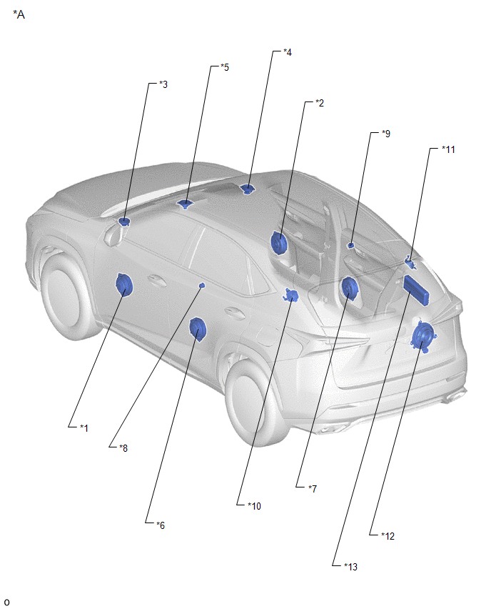
| *A | for 14 Speakers | - | - |
| *1 | FRONT NO. 1 SPEAKER ASSEMBLY LH | *2 | FRONT NO. 1 SPEAKER ASSEMBLY RH |
| *3 | FRONT NO. 2 SPEAKER ASSEMBLY LH | *4 | FRONT NO. 2 SPEAKER ASSEMBLY RH |
| *5 | FRONT NO. 3 SPEAKER ASSEMBLY | *6 | REAR SPEAKER ASSEMBLY LH |
| *7 | REAR SPEAKER ASSEMBLY RH | *8 | REAR NO. 2 SPEAKER ASSEMBLY LH |
| *9 | REAR NO. 2 SPEAKER ASSEMBLY RH | *10 | REAR HEADER SPEAKER ASSEMBLY LH |
| *11 | REAR HEADER SPEAKER ASSEMBLY RH | *12 | REAR NO. 3 SPEAKER ASSEMBLY |
| *13 | STEREO COMPONENT AMPLIFIER ASSEMBLY | - | - |
ILLUSTRATION
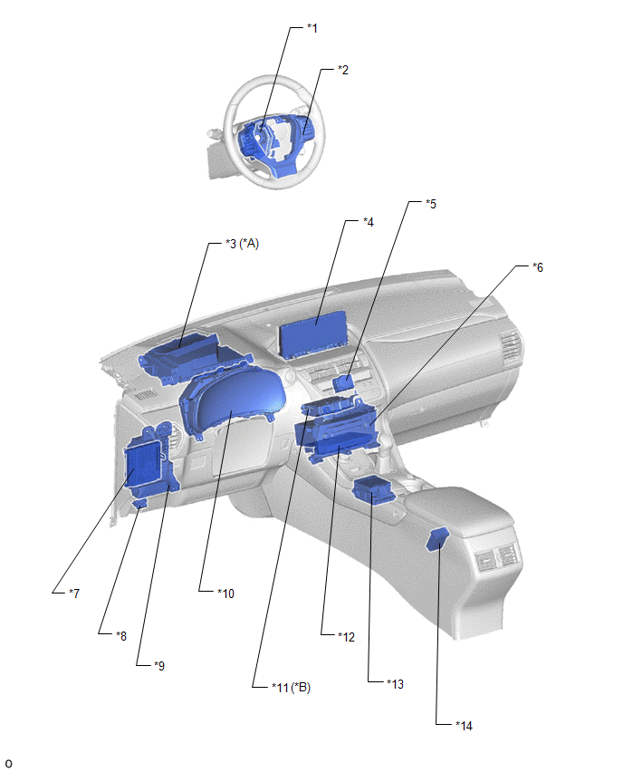
| *A | w/ Headup Display | *B | w/ Manual (SOS) Switch |
| *1 | SPIRAL CABLE SUB-ASSEMBLY | *2 | STEERING PAD SWITCH ASSEMBLY |
| *3 | COMBINATION METER MIRROR ECU | *4 | MULTI-DISPLAY ASSEMBLY |
| *5 | CLOCK ASSEMBLY | *6 | RADIO RECEIVER ASSEMBLY |
| *7 | MAIN BODY ECU (MULTIPLEX NETWORK BODY ECU) | *8 | DLC3 |
| *9 | INSTRUMENT PANEL JUNCTION BLOCK ASSEMBLY - ACC FUSE - ECU-IG NO.1 FUSE (w/ Headup Display) - ECU-IG NO.2 FUSE - IG2 NO.2 FUSE (w/ Manual [SOS] Switch) - PANEL FUSE - METER NO.2 FUSE | *10 | COMBINATION METER ASSEMBLY |
| *11 | DCM (TELEMATICS TRANSCEIVER) | *12 | NAVIGATION ECU |
| *13 | REMOTE OPERATION CONTROLLER ASSEMBLY (REMOTE TOUCH) | *14 | NO. 1 STEREO JACK ADAPTER ASSEMBLY |
READ NEXT:
 System Diagram
SYSTEM DIAGRAM
System Description
SYSTEM DESCRIPTION NAVIGATION SYSTEM OUTLINE (a) Vehicle position tracking methods It is essential that the navigation system correctly tracks the current vehicle position and displays it on the map.
How To Proceed With Troubleshooting
CAUTION / NOTICE / HINT HINT:
Use the following procedure to troubleshoot the navigation system.
*: Use the Techstream.
PROCEDURE 1. VEHICLE BROUGHT TO WORKSHOP
NEXT
SEE MORE:
Front Sensor Communication Malfunction (C1AEC)
DESCRIPTION This DTC is stored when there is an open or short circuit in the communication line between the front sensors and the ECU, or when there is a malfunction in a front sensor. DTC No. Detection Item DTC Detection Condition Trouble Area C1AEC Front Sensor Communication Malfunc
Automatic High Beam Camera (B124C)
DESCRIPTION The main body ECU (multiplex network body ECU) detects a high beam headlight illumination request signal of the automatic high beam system from the forward recognition camera. DTC No. Detection Item DTC Detection Condition Trouble Area B124C Automatic High Beam Camera Ma
