Lexus NX: Parts Location
PARTS LOCATION
ILLUSTRATION
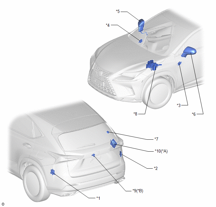
| *A | w/ Panoramic View Monitor System | *B | w/ Parking Assist Monitor System |
| *1 | BLIND SPOT MONITOR SENSOR LH (MASTER) | *2 | BLIND SPOT MONITOR SENSOR RH (SLAVE) |
| *3 | OUTER MIRROR CONTROL ECU ASSEMBLY LH | *4 | OUTER MIRROR CONTROL ECU ASSEMBLY RH |
| *5 | OUTER REAR VIEW MIRROR ASSEMBLY RH - OUTER MIRROR RH (OUTER REAR VIEW MIRROR INDICATOR RH) - OUTER MIRROR RETRACTOR RH | *6 | OUTER REAR VIEW MIRROR ASSEMBLY LH - OUTER MIRROR LH (OUTER REAR VIEW MIRROR INDICATOR LH) - OUTER MIRROR RETRACTOR LH |
| *7 | RCTA BUZZER (BLIND SPOT MONITOR BUZZER) | *8 | BRAKE BOOSTER WITH MASTER CYLINDER (SKID CONTROL ECU) |
| *9 | REAR TELEVISION CAMERA ASSEMBLY | *10 | PARKING ASSIST ECU |
ILLUSTRATION
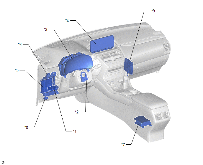
| *1 | BLIND SPOT MONITOR MAIN SWITCH (COMBINATION SWITCH ASSEMBLY) | *2 | STEERING SENSOR |
| *3 | COMBINATION METER ASSEMBLY | *4 | MULTI-DISPLAY ASSEMBLY |
| *5 | MAIN BODY ECU (MULTIPLEX NETWORK BODY ECU) | *6 | INSTRUMENT PANEL JUNCTION BLOCK ASSEMBLY - ECU-IG NO.1 FUSE - ECU-IG NO.2 FUSE |
| *7 | AIRBAG ECU ASSEMBLY | *8 | DLC3 |
| *9 | HYBRID VEHICLE CONTROL ECU | - | - |
READ NEXT:
 System Diagram
SYSTEM DIAGRAM
System Description
SYSTEM DESCRIPTION CAN COMMUNICATION SYSTEM (a) The blind spot monitor system uses CAN communication to transmit data between the right and left blind spot monitor sensors and each ECU. (b) If there i
How To Proceed With Troubleshooting
CAUTION / NOTICE / HINT HINT:
Use the following procedure to troubleshoot the blind spot monitor system.
*: Use the Techstream.
PROCEDURE 1. VEHICLE BROUGHT TO WORKSHOP
NEXT
SEE MORE:
Components
COMPONENTS ILLUSTRATION *A for 8 Inch Display *B for 10.3 Inch Display *1 CENTER INSTRUMENT CLUSTER FINISH PANEL ASSEMBLY *2 CONSOLE ARMREST ASSEMBLY *3 INSTRUMENT CLUSTER FINISH PANEL SUB-ASSEMBLY *4 INSTRUMENT PANEL FINISH PLATE *5 INSTRUMENT SIDE PANEL LH *6
Reassembly
REASSEMBLY CAUTION / NOTICE / HINT HINT:
Use the same procedure for the RH and LH sides.
The procedure listed below is for the LH side.
PROCEDURE 1. INSTALL REAR LIGHT SOCKET AND WIRE LH (a) Attach the wire harness clamp and connect the connector to install the rear light socket and wire LH.
