.gif)
- CH1 : Y26-1 (DS1) - Body ground
- CH2 : Y26-2 (DS2) - Body ground
Lexus NX: PBD Unit Pulse Sensor LH Circuit (B2226)
Lexus NX Service Manual / Vehicle Exterior / Door / Hatch / Power Back Door System / PBD Unit Pulse Sensor LH Circuit (B2226)
DESCRIPTION
This DTC is output when the multiplex network door ECU detects a power back door unit assembly set LH pulse malfunction.
| DTC No. | Detection Item | DTC Detection Condition | Trouble Area |
|---|---|---|---|
| B2226 | PBD Unit Pulse Sensor LH Circuit | Multiplex network door ECU detects power back door unit assembly set LH pulse malfunction |
|
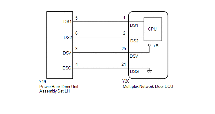
WIRING DIAGRAM
CAUTION / NOTICE / HINT
NOTICE:
If the replacement, removal and installation of the multiplex network door ECU or disconnection of the connectors of the multiplex network door ECU has been performed, initialize the power back door system.
Click here .gif)
PROCEDURE
| 1. | CHECK FOR DTC |
(a) Clear the DTCs.
Click here
(b) Check for DTCs.
Click here
OK:
DTC B2226 is not output
| OK | .gif) | USE SIMULATION METHOD TO CHECK |
|
| 2. | CHECK HARNESS AND CONNECTOR (MULTIPLEX NETWORK DOOR ECU - POWER BACK DOOR UNIT ASSEMBLY SET LH) |
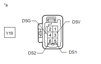
(a) Disconnect the Y26 multiplex network door ECU connector.
(b) Disconnect the Y19 power back door unit assembly set LH connector.
(c) Measure the resistance according to the value(s) in the table below.
Standard Resistance:
| Tester Connection | Condition | Specified Condition |
|---|---|---|
| Y26-21 (DSG) - Y19-4 (DSG) | Always | Below 1 Ω |
| Y26-25 (DSV) - Y19-3 (DSV) | Always | Below 1 Ω |
| Y26-2 (DS2) - Y19-6 (DS2) | Always | Below 1 Ω |
| Y26-1 (DS1) - Y19-5 (DS1) | Always | Below 1 Ω |
| Y26-21 (DSG) or Y19-4 (DSG) - Body ground | Always | 10 kΩ or higher |
| Y26-25 (DSV) or Y19-3 (DSV) - Body ground | Always | 10 kΩ or higher |
| Y26-2 (DS2) or Y19-6 (DS2) - Body ground | Always | 10 kΩ or higher |
| Y26-1 (DS1) or Y19-5 (DS1) - Body ground | Always | 10 kΩ or higher |
| NG | | REPAIR OR REPLACE HARNESS OR CONNECTOR |
|
| 3. | CHECK MULTIPLEX NETWORK DOOR ECU |
| (a) Disconnect the power back door unit assembly set LH connector. |
|
(b) Measure the resistance according to the value(s) in the table below.
Standard Resistance:
| Tester Connection | Condition | Specified Condition |
|---|---|---|
| Y19-4 (DSG) - Body ground | Always | Below 1 Ω |
(c) Measure the voltage according to the value(s) in the table below.
Standard Voltage:
| Tester Connection | Condition | Specified Condition |
|---|---|---|
| Y19-5 (DS1) - Body ground | Always | 7 V or higher |
| Y19-6 (DS2) - Body ground | Always | 7 V or higher |
| Y19-3 (DSV) - Body ground | Always | 7 V or higher |
| NG | | REPLACE MULTIPLEX NETWORK DOOR ECU |
|
| 4. | CHECK POWER BACK DOOR UNIT ASSEMBLY SET LH |
(a) Using an oscilloscope, check the waveform of each terminal from the rear of the multiplex network door ECU Y26 connector.
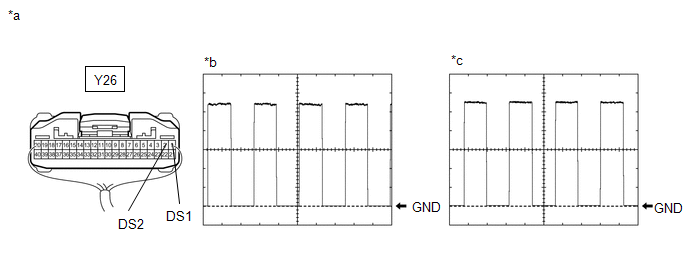
| *a | Component with harness connected (Multiplex Network Door ECU) | *b | Waveform (CH1) |
| *c | Waveform (CH2) | - | - |
Measurement Condition:
| Item | Condition |
|---|---|
| Tester Connection | |
| Tool setting | 2 V/DIV., 2 ms./DIV. |
| Vehicle condition | Open and close the back door by hand. |
HINT:
The period changes in accordance to the speed at which the back door is opened and closed by hand.
OK:
The waveform displayed is as shown in the illustration.
| OK | | REPLACE MULTIPLEX NETWORK DOOR ECU |
| NG | | REPLACE POWER BACK DOOR UNIT ASSEMBLY SET LH |
READ NEXT:
 PBD Unit Pulse Sensor RH Circuit (B2227)
DESCRIPTION This DTC is output when the multiplex network door ECU detects a power back door unit assembly set RH pulse malfunction. DTC No. Detection Item DTC Detection Condition Trouble Are
PBD Touch Sensor LH Circuit (B222A)
DESCRIPTION This DTC is output when the multiplex network door ECU detects a power back door sensor assembly LH touch sensor malfunction. DTC No. Detection Item DTC Detection Condition Troubl
PBD Touch Sensor RH Circuit (B222B)
DESCRIPTION This DTC is output when the multiplex network door ECU detects a power back door sensor assembly RH touch sensor malfunction. DTC No. Detection Item DTC Detection Condition Troubl
SEE MORE:
Fuel Level Sensor "A" Circuit Low (P0462,P0463)
DESCRIPTION Refer to DTC P0461. Click here DTC No. Detection Item DTC Detection Condition Trouble Area MIL Memory P0462 Fuel Level Sensor "A" Circuit Low Fuel sender gauge output resistance is less than 7 Ω for 30 seconds or more (1 trip detection logic).
Open or short
System Diagram
SYSTEM DIAGRAM Communication Table Sender Receiver Signal Line Radio Receiver Assembly Multi-display assembly Camera information signal GVIF Cable Radio Receiver Assembly Rear Television Camera Assembly Camera information signal CAN Communication Line Steering Sens
© 2016-2024 Copyright www.lexunx.com
