Lexus NX: Power Seat Position is not Memorized
DESCRIPTION
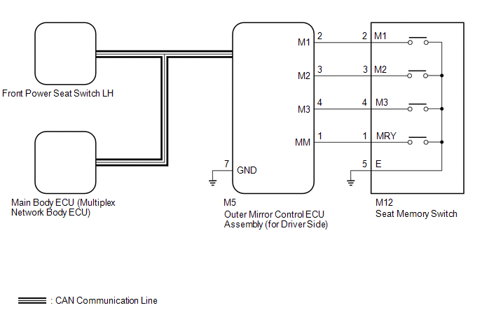
The main body ECU (multiplex network body ECU) receives seat memory switch signals from the outer mirror control ECU assembly (for Driver Side) via CAN communication. If the seat memory SET switch is being pressed when one of the M1, M2 or M3 switches is pressed, or if one of the M1, M2 or M3 switches is pressed within 3 seconds of pressing the seat memory SET switch, the main body ECU (multiplex network body ECU) sends a memory request signal to the front power seat switch LH. After receiving the request signal, the front power seat switch LH memorizes the location data of each motor.
WIRING DIAGRAM
CAUTION / NOTICE / HINT
NOTICE:
-
The front power seat control system (w/ Memory) uses the CAN communication system. First, confirm that there is no malfunction in the CAN communication system. Refer to the How to Proceed with Troubleshooting procedure.
Click here
.gif)
-
The seat position will not be stored if the SET switch and 2 or more of the seat memory switches (for example, M1 switch and M2 switch) are pressed simultaneously.
If a memorizing operation has failed, release all switches. The seat memory function does not operate unless the switches are released.
-
The seat will not return to the memorized position if 2 or more of the seat memory switches (for example, M1 switch and M2 switch) are pressed simultaneously.
If a restoring operation has failed, release all switches. The seat memory restoring function does not operate unless the switches are released.
-
Before replacing the main body ECU (multiplex network body ECU), refer to the Smart Access System with Push-button Start (for Entry Function).
Click here
PROCEDURE
| 1. | CHECK FRONT POWER SEAT OPERATION |
(a) Check that each function of the power seat operates normally by using the front power seat switch LH.
Click here
OK:
Each function of the power seat operates normally using the front power seat switch LH.
| NG | .gif) | GO TO PROBLEM SYMPTOMS TABLE |
|
.gif)
| 2. | READ VALUE USING TECHSTREAM (SEAT MEMORY SWITCH1, SEAT MEMORY SWITCH2, SEAT MEMORY SWITCH3, SEAT MEMORY SET SW) |
(a) Connect the Techstream to the DLC3.
(b) Turn the power switch on (IG).
(c) Turn the Techstream on.
(d) Enter the following menus: Body Electrical / Mirror L / Data List.
(e) Read the Data List according to the display on the Techstream.
Body Electrical > Mirror L > Data List| Tester Display | Measurement Item | Range | Normal Condition | Diagnostic Note |
|---|---|---|---|---|
| Seat Memory Switch1 | M1 switch | ON or OFF | ON: M1 switch on OFF: M1 switch off | - |
| Seat Memory Switch2 | M2 switch | ON or OFF | ON: M2 switch on OFF: M2 switch off | - |
| Seat Memory Switch3 | M3 switch | ON or OFF | ON: M3 switch on OFF: M3 switch off | - |
| Seat Memory Set SW | SET switch | ON or OFF | ON: SET switch on OFF: SET switch off | - |
| Tester Display |
|---|
| Seat Memory Switch1 |
| Seat Memory Switch2 |
| Seat Memory Switch3 |
| Seat Memory Set SW |
OK:
The Techstream display changes correctly in response to the switch operation.
| NG | | GO TO STEP 6 |
|
| 3. | PERFORM ACTIVE TEST USING TECHSTREAM (BUZZER) |
(a) Connect the Techstream to the DLC3.
(b) Turn the power switch on (IG).
(c) Turn the Techstream on.
(d) Enter the following menus: Body Electrical / Driver Seat / Active Test.
(e) Read the Data List according to the display on the Techstream.
Body Electrical > Driver Seat > Active Test| Tester Display | Measurement Item | Control Range | Diagnostic Note |
|---|---|---|---|
| Buzzer | Buzzer operation | OFF/ON | - |
| Tester Display |
|---|
| Buzzer |
OK:
Buzzer sounds/stops normally using the Techstream operation.
| NG | | REPLACE FRONT POWER SEAT SWITCH LH |
|
| 4. | REPLACE OUTER MIRROR CONTROL ECU ASSEMBLY (for Driver Side) |
(a) Replace the outer mirror control ECU assembly (for Driver Side) with a new or known good one.
Click here
|
| 5. | CHECK SEAT POSITION MEMORY AND RESTORING FUNCTION |
(a) Check that the seat position memory and restoring function.
Click here
OK:
Seat position memory and restoring function operate normally.
| OK | | END (OUTER MIRROR CONTROL ECU ASSEMBLY [for Driver Side] WAS DEFECTIVE) |
| NG | | REPLACE FRONT POWER SEAT SWITCH LH |
| 6. | INSPECT SEAT MEMORY SWITCH |
(a) Remove the seat memory switch.
Click here
(b) Inspect the seat memory switch.
Click here
| NG | | REPLACE SEAT MEMORY SWITCH |
|
| 7. | CHECK HARNESS AND CONNECTOR (OUTER MIRROR CONTROL ECU ASSEMBLY [for Driver Side] - SEAT MEMORY SWITCH AND BODY GROUND) |
(a) Disconnect the M5 outer mirror control ECU assembly (for Driver Side) connector.
(b) Disconnect the M12 seat memory switch connector.
(c) Measure the resistance according to the value(s) in the table below.
Standard Resistance:
| Tester Connection | Condition | Specified Condition |
|---|---|---|
| M5-1 (MM) - M12-1 (MRY) | Always | Below 1 Ω |
| M5-1 (MM) or M12-1 (MRY) - Body ground | Always | 10 kΩ or higher |
| M5-2 (M1) - M12-2 (M1) | Always | Below 1 Ω |
| M5-2 (M1) or M12-2 (M1) - Body ground | Always | 10 kΩ or higher |
| M5-3 (M2) - M12-3 (M2) | Always | Below 1 Ω |
| M5-3 (M2) or M12-3 (M2) - Body ground | Always | 10 kΩ or higher |
| M5-4 (M3) - M12-4 (M3) | Always | Below 1 Ω |
| M5-4 (M3) or M12-4 (M3) - Body ground | Always | 10 kΩ or higher |
| M5-7 (GND) - Body ground | Always | Below 1 Ω |
| M12-5 (E) - Body ground | Always | Below 1 Ω |
| OK | | REPLACE OUTER MIRROR CONTROL ECU ASSEMBLY (for Driver Side) |
| NG | | REPAIR OR REPLACE HARNESS OR CONNECTOR |
READ NEXT:
 Power Seat does not Return to Memorized Position
DESCRIPTION When either the M1, M2 or M3 switch is pressed, the outer mirror control ECU assembly (for Driver Side) sends a switch signal to the main body ECU (multiplex network body ECU) via CAN comm
Wireless Transmitter Memory Function does not Operate
DESCRIPTION With the power switch on (IG) and the driver door closed, pressing the manual lock or unlock switch on the multiplex network master switch assembly while holding a seat memory switch (M1,
Wireless-linked Return Function does not Operate
DESCRIPTION When a door is unlocked using the wireless unlock function, the certification ECU (smart key ECU assembly) sends a key ID signal to the main body ECU (multiplex network body ECU). When a d
SEE MORE:
Customize Parameters
CUSTOMIZE PARAMETERS CUSTOMIZE LIGHTING SYSTEM (EXT) NOTICE:
When the customer requests a change in a function, first make sure that the function can be customized.
Record the current settings before customizing.
HINT: The following items can be customized. (a) Customizing with the Techstrea
Components
COMPONENTS ILLUSTRATION *1 FRONT SEAT INNER BELT ASSEMBLY LH *2 FRONT SEAT INNER BELT ASSEMBLY RH *3 FRONT SEAT BELT ANCHOR PLATE - - N*m (kgf*cm, ft.*lbf): Specified torque - -
