Lexus NX: Power Source Circuit
DESCRIPTION
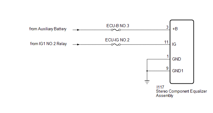
This circuit is the power source circuit for the stereo component equalizer assembly.
WIRING DIAGRAM
CAUTION / NOTICE / HINT
NOTICE:
Inspect the fuses for circuits related to this system before performing the following procedure.
PROCEDURE
| 1. | CHECK HARNESS AND CONNECTOR (STEREO COMPONENT EQUALIZER ASSEMBLY - BATTERY AND BODY GROUND) |
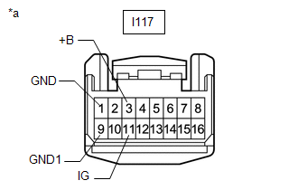
| (a) Disconnect the stereo component equalizer assembly connector. |
|
(b) Measure the resistance according to the value(s) in the table below.
Standard Resistance:
| Tester Connection | Condition | Specified Condition |
|---|---|---|
| I117-1 (GND) - Body ground | Always | Below 1 Ω |
| I117-9 (GND1) - Body ground | Always | Below 1 Ω |
(c) Measure the voltage according to the value(s) in the table below.
Standard Voltage:
| Tester Connection | Switch Condition | Specified Condition |
|---|---|---|
| I117-3 (+B) - Body ground | Power switch off | 11 to 14 V |
| I117-11 (IG) - Body ground | Power switch on (IG) | 11 to 14 V |
| OK | .gif) | PROCEED TO NEXT SUSPECTED AREA SHOWN IN PROBLEM SYMPTOMS TABLE |
| NG | | REPAIR OR REPLACE HARNESS OR CONNECTOR |
READ NEXT:
 Precaution
PRECAUTION PRECAUTION FOR DISCONNECTING CABLE FROM NEGATIVE AUXILIARY BATTERY TERMINAL NOTICE: After the power switch is turned off, the radio receiver assembly records various types of memory and set
Parts Location
PARTS LOCATION ILLUSTRATION *1 NO. 2 ENGINE ROOM RELAY BLOCK - DCM FUSE (w/ Manual [SOS] Switch) - ECU-B NO.5 FUSE - ECU-B NO.1 FUSE *2 NO. 1 ENGINE ROOM RELAY BLOCK - AMP FUSE - RADIO FUSE
SEE MORE:
Diagnosis System
DIAGNOSIS SYSTEM DESCRIPTION (a) Sliding roof system data and Diagnostic Trouble Codes (DTCs) can be read through the vehicle Data Link Connector 3 (DLC3). When the system seems to be malfunctioning, use the Techstream to check for malfunctions and perform repairs. CHECK DLC3 (a) Check the DLC3. Cli
Removal
REMOVAL CAUTION / NOTICE / HINT HINT:
Use the same procedure for the RH and LH sides.
The procedures listed below are for the LH side.
PROCEDURE 1. REMOVE FRONT DOOR LOWER OUTSIDE MOULDING SUB-ASSEMBLY LH HINT: When removing the front door lower outside moulding sub-assembly LH, heat the fro
