Lexus NX: Pre-collision System Warning Buzzer
Components
COMPONENTS
ILLUSTRATION
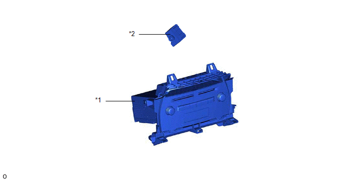
| *1 | RADIO RECEIVER ASSEMBLY | *2 | SKID CONTROL BUZZER ASSEMBLY (PRE-COLLISION SYSTEM WARNING BUZZER) |
Inspection
INSPECTION
PROCEDURE
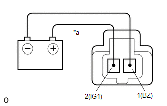
1. INSPECT SKID CONTROL BUZZER ASSEMBLY (PRE-COLLISION SYSTEM WARNING BUZZER)
| (a) Apply battery voltage and check the operation of the skid control buzzer assembly (pre-collision system warning buzzer) according to the table below. OK:
If the result is not as specified, replace the skid control buzzer assembly (pre-collision system warning buzzer). |
|
Removal
REMOVAL
PROCEDURE
1. REMOVE RADIO RECEIVER ASSEMBLY
Click here .gif)
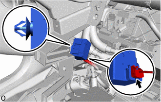
2. REMOVE SKID CONTROL BUZZER ASSEMBLY (PRE-COLLISION SYSTEM WARNING BUZZER)
(a) Using a clip remover, disconnect the clamp.
| (b) Disconnect the connector and remove the skid control buzzer assembly (pre-collision system warning buzzer). |
|
Installation
INSTALLATION
PROCEDURE
1. INSTALL SKID CONTROL BUZZER ASSEMBLY (PRE-COLLISION SYSTEM WARNING BUZZER)
(a) Connect the connector.
(b) Install the skid control buzzer assembly (pre-collision system warning buzzer) with the clamp.
2. INSTALL RADIO RECEIVER ASSEMBLY
Click here .gif)
READ NEXT:
 Precaution
PRECAUTION FOR OPERATION OF ELECTRICAL ITEMS RESTRICTED NOTICE:
If the auxiliary battery voltage is low, the climate control seat system may not operate. When "High Power Consumption / Partial Limi
SEE MORE:
Blind Spot Monitor Master Module Beam Axis Inspection Incomplete (C1ABB)
DESCRIPTION This DTC is stored when a beam axis inspection has not been performed for the blind spot monitor sensor LH. HINT: This DTC is always stored after replacing a blind spot monitor sensor. The purpose of this DTC is to ensure that beam axis inspection is performed. Completing the beam axis i
Dtc Check / Clear
DTC CHECK / CLEAR CHECK DTC (a) Connect the Techstream to the DLC3. (b) Turn the power switch on (IG). (c) Turn the Techstream on. (d) Enter the following menus: Body Electrical / Pre-Collision System / Trouble Codes. Body Electrical > Pre-Collision System > Trouble Codes (e) Check for DTCs.
