Lexus NX: Radio Receiver Power Source Circuit
DESCRIPTION
This is the power source circuit to operate the radio receiver assembly.
WIRING DIAGRAM

CAUTION / NOTICE / HINT
NOTICE:
- Inspect the fuses for circuits related to this system before performing the following procedure.
-
When replacing the radio receiver assembly, always replace it with a new one.
If a radio receiver assembly which was installed to another vehicle is used, the following may occur:
- A communication malfunction DTC may be stored.
- The radio receiver assembly may not operate normally.
HINT:
Depending on the parts that are replaced during vehicle inspection or maintenance, performing initialization, registration or calibration may be needed. Refer to Precaution for Audio and Visual System.
Click here .gif)
PROCEDURE
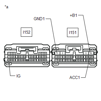
| 1. | CHECK HARNESS AND CONNECTOR (RADIO RECEIVER ASSEMBLY - BATTERY AND BODY GROUND) |
| (a) Disconnect the I151 and I152 radio receiver assembly connectors. |
|
(b) Measure the resistance according to the value(s) in the table below.
Standard Resistance:
| Tester Connection | Condition | Specified Condition |
|---|---|---|
| I151-1 (GND1) - Body ground | Always | Below 1 Ω |
(c) Measure the voltage according to the value(s) in the table below.
Standard Voltage:
| Tester Connection | Condition | Specified Condition |
|---|---|---|
| I151-4 (+B1) - I151-1 (GND1) | Power switch off | 11 to 14 V |
| I151-15 (ACC1) - I151-1 (GND1) | Power switch on (ACC) | 11 to 14 V |
| I152-19 (IG) - I151-1 (GND1) | Power switch on (IG) | 11 to 14 V |
| OK | .gif) | PROCEED TO NEXT SUSPECTED AREA SHOWN IN PROBLEM SYMPTOMS TABLE |
| NG | | REPAIR OR REPLACE HARNESS OR CONNECTOR |
READ NEXT:
 Components
COMPONENTS ILLUSTRATION *A w/o Power Back Door *B w/ Power Back Door *C for 10 Speakers *D for 14 Speakers *1 BACK DOOR CENTER GARNISH *2 BACK DOOR FINISH COVER LH *3
Removal
REMOVAL PROCEDURE 1. REMOVE BACK DOOR CENTER GARNISH Click here 2. REMOVE BACK DOOR SIDE GARNISH LH Click here 3. REMOVE BACK DOOR SIDE GARNISH RH Click here 4. REMOVE BACK DOOR TRIM BASE (w/
SEE MORE:
How To Proceed With Troubleshooting
CAUTION / NOTICE / HINT HINT:
Use these procedures to troubleshoot the power steering system.
*: Use the Techstream.
PROCEDURE 1. VEHICLE BROUGHT TO WORKSHOP
NEXT 2. INSPECT AUXILIARY BATTERY VOLTAGE (a) Measure the voltage of the auxiliary battery. Standar
Disposal
DISPOSAL CAUTION / NOTICE / HINT HINT: The tire pressure warning valve and transmitter is powered by a lithium battery. When disposing of the tire pressure warning valve and transmitter, remove the battery and dispose of it properly. PROCEDURE 1. DISPOSE OF TIRE PRESSURE WARNING VALVE AND TRANSMITTE
