Lexus NX: Rear Power Seat Switch Circuit
DESCRIPTION
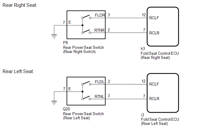
When the rear power seat switch is operated, a recline signal is sent to the fold seat control ECU. The ECU activates the power seat motor based on the signal from the rear power seat switch.
WIRING DIAGRAM
PROCEDURE
| 1. | INSPECT REAR POWER SEAT SWITCH |
(a) Remove the rear power seat switch.
Click here .gif)
(b) Inspect the rear power seat switch.
Click here
| NG | .gif) | REPLACE REAR POWER SEAT SWITCH |
|
.gif)
| 2. | CHECK HARNESS AND CONNECTOR (REAR POWER SEAT SWITCH - FOLD SEAT CONTROL ECU AND BODY GROUND) |
(a) Rear Right Seat:
(1) Disconnect the P8 rear power seat switch connector.
(2) Disconnect the h3 fold seat control ECU connector.
(b) Rear Left Seat:
(1) Disconnect the Q20 rear power seat switch connector.
(2) Disconnect the i3 fold seat control ECU connector.
(c) Measure the resistance according to the value(s) in the table below.
Standard Resistance:
Rear Right Seat| Tester Connection | Condition | Specified Condition |
|---|---|---|
| P8-3 (FLDR) - h3-12 (RCLF) | Always | Below 1 Ω |
| P8-3 (FLDR) or h3-12 (RCLF) - Body ground | Always | 10 kΩ or higher |
| P8-2 (RTNR) - h3-7 (RCLR) | Always | Below 1 Ω |
| P8-2 (RTNR) or h3-7 (RCLR) - Body ground | Always | 10 kΩ or higher |
| P8-7 (E) - Body ground | Always | Below 1 Ω |
| Tester Connection | Condition | Specified Condition |
|---|---|---|
| Q20-2 (FLDL) - i3-12 (RCLF) | Always | Below 1 Ω |
| Q20-2 (FLDL) or i3-12 (RCLF) - Body ground | Always | 10 kΩ or higher |
| Q20-3 (RTNL) - i3-7 (RCLR) | Always | Below 1 Ω |
| Q20-3 (RTNL) or i3-7 (RCLR) - Body ground | Always | 10 kΩ or higher |
| Q20-7 (E) - Body ground | Always | Below 1 Ω |
| OK | | PROCEED TO NEXT SUSPECTED AREA SHOWN IN PROBLEM SYMPTOMS TABLE |
| NG | | REPAIR OR REPLACE HARNESS OR CONNECTOR |
READ NEXT:
 Components
COMPONENTS ILLUSTRATION *1 BENCH TYPE REAR SEAT CUSHION ASSEMBLY *2 DECK BOARD ASSEMBLY *3 NO. 2 BATTERY SERVICE COVER BOARD *4 NO. 3 BATTERY SERVICE COVER BOARD *5 TONNEAU C
Removal
REMOVAL CAUTION / NOTICE / HINT CAUTION: Wear protective gloves. Sharp areas on the parts may injure your hands. PROCEDURE 1. REMOVE TONNEAU COVER ASSEMBLY Click here 2. REMOVE DECK BOARD ASSEMBLY
SEE MORE:
Inspection
INSPECTION PROCEDURE 1. INSPECT REAR NO. 1 SEAT OUTER BELT ASSEMBLY (a) Before installing the rear No. 1 seat outer belt assembly, check the ELR function. NOTICE: Do not disassemble the retractor. (1) When the inclination of the retractor is 15° or less, check that the belt can be pulled from th
Adjustment
ADJUSTMENT PROCEDURE 1. STEERING OFF CENTER ADJUSTMENT HINT: This is the adjustment procedure for when the steering is off-center. (a) Check if the steering wheel is off-center. (1) Apply masking tape to the top center of the steering wheel and upper steering column cover. *1 Steer
