Lexus NX: Rear Window Defogger System does not Operate
DESCRIPTION
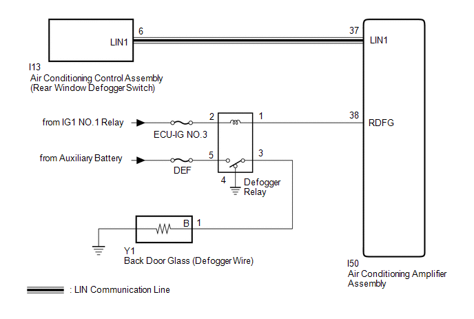
When the rear window defogger switch on the air conditioning control assembly is pressed, the operation signal is transmitted to the air conditioning amplifier assembly via LIN communication. When the air conditioning amplifier assembly receives the signal, it turns on the defogger relay to operate the window defogger system.
WIRING DIAGRAM
CAUTION / NOTICE / HINT
NOTICE:
- Inspect the fuses for circuits related to this system before performing the following procedure.
-
The window defogger system uses the LIN communication system. Inspect the communication function by following How to Proceed with Troubleshooting. Troubleshoot the window defogger system after confirming that the communication system is functioning properly.
Click here
.gif)
-
If the auxiliary battery voltage becomes low, windshield deicer operation is canceled to prioritize supplying power to the power steering system.
for Power Tilt and Power Telescopic Steering Column: Click here
for Manual Tilt and Manual Telescopic Steering Column: Click here
PROCEDURE
| 1. | CHECK AIR CONDITIONING SYSTEM |
(a) Check the air conditioning system.
Click here
HINT:
Both the window defogger system operation signal and air conditioning system operation signal are transmitted to the air conditioning amplifier assembly via the same communication line.
OK:
The air conditioning system operates normally.
| NG | .gif) | GO TO AIR CONDITIONING SYSTEM |
|
.gif)
| 2. | CHECK AIR CONDITIONING CONTROL ASSEMBLY |
(a) Check that the defogger indicator illuminates when the window defogger switch is on.
OK:
Defogger indicator illuminates.
| NG | | REPLACE AIR CONDITIONING CONTROL ASSEMBLY |
|
| 3. | PERFORM ACTIVE TEST USING TECHSTREAM |
(a) Using the Techstream, perform the Active Test.
Click here
| Tester Display | Measurement Item | Control Range | Diagnostic Note |
|---|---|---|---|
| Defogger Relay (Rear) | Defogger relay | OFF or ON | - |
| Tester Display |
|---|
| Defogger Relay (Rear) |
OK:
Back door glass (defogger wire) warms up.
| NG | | GO TO STEP 5 |
|
| 4. | CHECK AIR CONDITIONING AMPLIFIER ASSEMBLY |
(a) Temporarily replace the air conditioning amplifier assembly with a new or normally functioning one.
Click here
(b) Check that the window defogger system operates normally.
OK:
The window defogger system operates normally.
| OK | | END (AIR CONDITIONING AMPLIFIER ASSEMBLY IS DEFECTIVE) |
| NG | | REPLACE AIR CONDITIONING CONTROL ASSEMBLY |
| 5. | CHECK HARNESS AND CONNECTOR (BACK DOOR GLASS - BATTERY) |
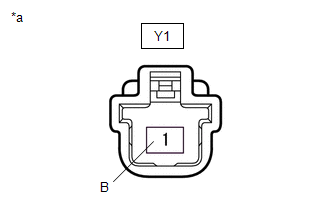
| (a) Disconnect the back door glass (defogger wire) connector. |
|
(b) Measure the voltage according to the value(s) in the table below.
Standard Voltage:
| Tester Connection | Switch Condition | Specified Condition |
|---|---|---|
| Y1-1 (B) - Body ground | Power switch on (IG), rear window defogger switch on | 11 to 14 V |
| Power switch on (IG), rear window defogger switch off | Below 1 V |
| OK | | REPLACE BACK DOOR GLASS (DEFOGGER WIRE) |
|
| 6. | INSPECT DEFOGGER RELAY |
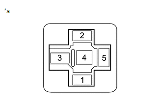
(a) Remove the defogger relay from the No. 2 engine room relay block.
(b) Inspect the defogger relay.
Click here
| NG | | REPLACE DEFOGGER RELAY |
|
| 7. | CHECK HARNESS AND CONNECTOR (DEFOGGER RELAY - BATTERY) |
| (a) Remove the defogger relay from the No. 2 engine room relay block. |
|
(b) Measure the voltage according to the value(s) in the table below.
Standard Voltage:
| Tester Connection | Switch Condition | Specified Condition |
|---|---|---|
| Defogger relay terminal 2 - Body ground | Power switch on (IG) | 11 to 14 V |
| Defogger relay terminal 5 - Body ground | Power switch off | 11 to 14 V |
| NG | | REPAIR OR REPLACE HARNESS OR CONNECTOR |
|
| 8. | CHECK HARNESS AND CONNECTOR (DEFOGGER RELAY - AIR CONDITIONING AMPLIFIER ASSEMBLY AND BACK DOOR GLASS) |
(a) Remove the defogger relay from the No. 2 engine room relay block.
(b) Disconnect the Y1 back door glass (defogger wire) connector.
(c) Disconnect the I50 air conditioning amplifier assembly connector.
(d) Measure the resistance according to the value(s) in the table below.
Standard Resistance:
| Tester Connection | Condition | Specified Condition |
|---|---|---|
| Defogger relay terminal 1 - I50-38 (RDFG) | Always | Below 1 Ω |
| Defogger relay terminal 3 - Y1-1 (B) | Always | Below 1 Ω |
| Defogger relay terminal 1 or I50-38 (RDFG) - Body ground | Always | 10 kΩ or higher |
| Defogger relay terminal 3 or Y1-1 (B) - Body ground | Always | 10 kΩ or higher |
| OK | | REPLACE AIR CONDITIONING AMPLIFIER ASSEMBLY |
| NG | | REPAIR OR REPLACE HARNESS OR CONNECTOR |
READ NEXT:
 Parts Location
PARTS LOCATION ILLUSTRATION *1 FRONT WIPER DEICER RELAY *2 AIR CONDITIONING AMPLIFIER ASSEMBLY *3 MULTI-DISPLAY ASSEMBLY *4 RADIO RECEIVER ASSEMBLY *5 WINDSHIELD GLASS - WIND
System Diagram
SYSTEM DIAGRAM Communication Table Transmitter Receiver Signal Communication Method Multi-display Assembly Radio Receiver Assembly Windshield deicer switch signal GVIF Radio Re
SEE MORE:
Power Outlet Socket
ComponentsCOMPONENTS ILLUSTRATION *A w/ Rear Seat Heater - - *1 CIGARETTE LIGHTER COVER *2 NO. 2 POWER OUTLET SOCKET ASSEMBLY *3 REAR CONSOLE END PANEL SUB-ASSEMBLY - - RemovalREMOVAL PROCEDURE 1. REMOVE REAR CONSOLE END PANEL SUB-ASSEMBLY Click here 2. REMOVE C
System Information not Received (C13AE)
DESCRIPTION DTC No. Detection Item DTC Detection Condition Trouble Area Memory Note C13AE System Information not Received Both of following conditions are met:
Power switch is on (IG)
After parking brake ECU assembly is replaced, when power switch is first turned on (IG), s
