Lexus NX: Reassembly
REASSEMBLY
CAUTION / NOTICE / HINT
HINT:
- Use the same procedure for the RH and LH side.
- The procedure listed below is for the LH side.
-
A bolt without a torque specification is shown in the standard bolt chart.
Click here
.gif)
PROCEDURE
1. REPAIR INSTRUCTION
Click here
2. INSTALL NO. 1 BLACK OUT TAPE LH
Click here
3. INSTALL NO. 2 BLACK OUT TAPE LH
Click here
4. INSTALL NO. 3 BLACK OUT TAPE LH
Click here
5. INSTALL FRONT DOOR OUTSIDE MOULDING SUB-ASSEMBLY LH
Click here
6. INSTALL FRONT DOOR REAR WINDOW FRAME MOULDING LH
Click here
7. INSTALL HOLE PLUG
(a) Install the hole plug.
8. INSTALL FRONT DOOR PANEL CUSHION
(a) Install the 2 front door panel cushions.
9. INSTALL FRONT DOOR BELT MOULDING ASSEMBLY LH
Click here
10. INSTALL FRONT DOOR UPPER OUTSIDE MOULDING PAD
Click here
11. INSTALL FRONT DOOR LOWER OUTSIDE MOULDING SUB-ASSEMBLY LH
Click here
12. INSTALL FRONT DOOR WEATHERSTRIP LH
(a) Attach the 24 clips to install the front door weatherstrip LH.
13. INSTALL UPPER DOOR FRAME GARNISH LH
(a) Install a new upper door frame garnish LH.
14. INSTALL FRONT DOOR CHECK ASSEMBLY LH
(a) Apply MP grease to the sliding area of the front door check assembly LH.
(b) When reusing a bolt:
(1) Clean the threads of the bolt with non-residue solvent.
(2) Apply adhesive to the threads of the bolt.
Adhesive:
Toyota Genuine Adhesive 1324, Three Bond 1324 or equivalent.
(c) Install the front door check assembly LH to the door panel with the 2 nuts.
Torque:
8.0 N·m {82 kgf·cm, 71 in·lbf}
(d) Install the front door check assembly LH to the body panel with the bolt.
Torque:
27 N·m {275 kgf·cm, 20 ft·lbf}
15. INSTALL FRONT DOOR LOCK ASSEMBLY LH
Click here
16. INSTALL DOOR OUTSIDE HANDLE BUSH
(a) Install the door outside handle bush.
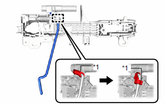
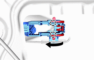
17. INSTALL FRONT DOOR LOCK OPEN ROD LH
(a) Install the front door lock open rod LH to the front door outside handle frame sub-assembly LH.
| (b) Rotate the snap as shown in the illustration to attach the snap to the front door lock open rod LH. |
|
18. INSTALL FRONT DOOR OUTSIDE HANDLE FRAME SUB-ASSEMBLY LH
| (a) Apply MP grease to the sliding area of the front door outside handle frame sub-assembly LH. |
|
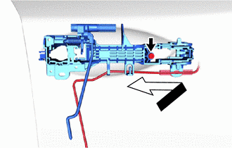
(b) Using a T30 "TORX" socket wrench, install the front door outside handle frame sub-assembly LH with the screw as shown in the illustration.
Torque:
4.0 N·m {41 kgf·cm, 35 in·lbf}
(c) Attach the clamp.
19. INSTALL FRONT DOOR FRONT OUTSIDE HANDLE PAD
(a) Attach the 3 claws to install the front door front outside handle pad.
20. INSTALL FRONT DOOR REAR OUTSIDE HANDLE PAD
(a) Attach the 4 claws to install the front door rear outside handle pad.
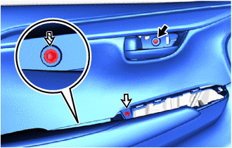
21. INSTALL FRONT DOOR LOCK CYLINDER ASSEMBLY LH (for Driver Side)
(a) Using a mechanical key, temporarily install the front door lock cylinder assembly LH as shown in the illustration.
| *a | 30° | - | - |
| (b) Using a T30 "TORX" socket wrench, install the front door lock cylinder assembly LH with the screw. |
|
.png)
(c) Install the hole plug.
22. INSTALL FRONT DOOR OUTSIDE HANDLE COVER RH (for Front Passenger Side)
| (a) Using a T30 "TORX" socket wrench, install the front door outside handle cover RH with the screw. |
|
.png)
(b) Install the hole plug.
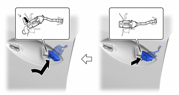
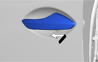
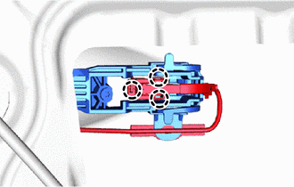
23. INSTALL FRONT DOOR OUTSIDE HANDLE ASSEMBLY LH
| (a) Temporarily install the front door outside handle assembly LH in the direction of the arrow shown in the illustration. |
|
| (b) Attach the 2 claws to install the holder to the front door outside handle assembly LH. |
|
| (c) Attach the 3 claws to connect the connector and connector cover. |
|
24. INSTALL FRONT DOOR REAR LOWER FRAME SUB-ASSEMBLY LH
(a) Attach the guide to install the front door rear lower frame sub-assembly LH with the bolt.
25. INSTALL FRONT DOOR NO. 1 STIFFENER CUSHION
(a) Clean vehicle installation surface.
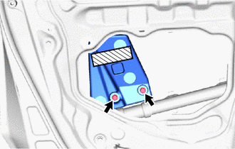
.png) | Double-sided tape |
(1) Remove any remaining double-sided tape from the vehicle installation surface.
(2) Clean the front door panel sub-assembly RH installation surface with non-residue solvent.
(b) Remove the peeling paper on a new front door No. 1 stiffener cushion while making sure not to touch the adhesional surface.
(c) Install the front door No. 1 stiffener cushion with the 2 bolts.
Torque:
6.2 N·m {63 kgf·cm, 55 in·lbf}
(d) Press the front door No. 1 stiffener cushion against the door panel.
26. INSTALL FRONT DOOR WINDOW REGULATOR SUB-ASSEMBLY LH
| (a) Apply MP grease to the sliding and rotating areas of the front door window regulator sub-assembly LH. |
|
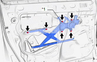
(b) Temporarily install the temporarily bolt to the front door window regulator sub-assembly LH.
(c) Install the front door window regulator sub-assembly LH with the 5 bolts, and then tighten the temporarily bolt.
Torque:
8.0 N·m {82 kgf·cm, 71 in·lbf}
HINT:
Tighten the bolts in the order shown in the illustration.
NOTICE:
Be careful not to drop the front door window regulator as it may become damaged.
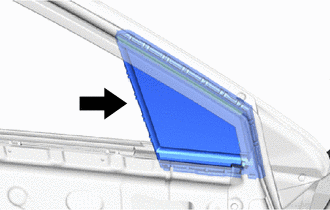
27. INSTALL FRONT DOOR FIX WINDOW WEATHERSTRIP LH
(a) Install the front door fix window weatherstrip LH.
28. INSTALL FRONT DOOR FIX WINDOW GLASS LH
| (a) Install the front door fix window glass LH in the direction indicated by the arrow in the illustration. |
|
29. INSTALL FRONT DOOR FRONT LOWER FRAME SUB-ASSEMBLY LH
(a) Lift up the weatherstrip, and then install the front door front lower frame sub-assembly LH with the screw.
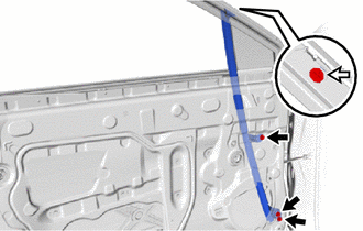
.png) | Bolt |
.png) | Screw |
(b) Install the 3 bolts.
Torque:
6.2 N·m {63 kgf·cm, 55 in·lbf}
30. INSTALL FRONT DOOR GLASS SUB-ASSEMBLY LH
(a) Temporarily install the power window regulator master switch assembly with front door armrest base panel.
(b) Connect the cable to the auxiliary battery negative (-) terminal.
(c) Move the front door window regulator so that the front door glass bolts can be seen.
(d) Disconnect the cable from the auxiliary battery negative (-) terminal.
CAUTION:
Wait at least 90 seconds after disconnecting the cable from the auxiliary battery negative (-) terminal to disable the SRS system.
NOTICE:
When disconnecting the cable, some systems need to be initialized after the cable is reconnected.
Click here
| (e) Insert the front door glass sub-assembly LH in the door panel sub-assembly LH in the order shown in the illustration. NOTICE: Be careful not to damage the front door glass sub-assembly LH. |
|
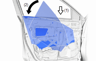
(f) Install the front door glass sub-assembly LH with the 2 bolts.
Torque:
8.0 N·m {82 kgf·cm, 71 in·lbf}
(g) Install the hole plug.
31. INSTALL FRONT DOOR GLASS RUN LH
(a) Install the front door glass run LH.
32. INSTALL DOOR SIDE AIR BAG SENSOR LH
Click here
33. INSTALL FRONT DOOR SERVICE HOLE COVER LH
(a) Apply new butyl tape to the front door panel.
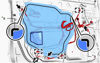
| *a | Reference Point |
| | Connector |
| | Bolt |
(b) Pass each cable and connector through a new front door service hole cover LH.
(c) Attach the front door service hole cover LH by aligning it with the reference points on the front door panel.
HINT:
Securely install the front door service hole cover LH by attaching it without any wrinkles or air bubbles.
(d) Attach the 3 clamps.
(e) Install the ground wire with the bolt.
(f) Connect the 3 connectors.
34. INSTALL FRONT NO. 1 SPEAKER ASSEMBLY
Click here
35. INSTALL OUTER REAR VIEW MIRROR ASSEMBLY LH
Click here
36. INSTALL OUTER MIRROR INSTALL HOLE COVER LH
Click here
37. INSTALL OUTER MIRROR CONTROL ECU ASSEMBLY
Click here
38. INSTALL FRONT DOOR ARMREST SET BRACKET LH
(a) Install the front door armrest set bracket LH with the 2 screws.
39. INSTALL FRONT DOOR INNER GLASS WEATHERSTRIP LH
(a) Install the front door inner glass weatherstrip LH.
40. INSTALL FRONT SEAT SLIDE SWITCH BEZEL (for Driver Side with Memory)
Click here
41. INSTALL SEAT MEMORY SWITCH (for Driver Side with Memory)
Click here
42. INSTALL FRONT DOOR INSIDE HANDLE SUB-ASSEMBLY LH
(a) Install the front door inside handle sub-assembly LH with the 6 screws.
43. INSTALL FRONT DOOR TRIM BOARD SUB-ASSEMBLY LH
| (a) Connect the front door lock remote control cable assembly LH and front door inside locking cable assembly LH. |
|
.png)
(b) Attach the 2 clamps.
(c) for Driver Side with Memory:
(1) Disconnect the connector.
| (d) Attach the 8 clips to install the front door trim board sub-assembly LH. |
|
.png)
(e) Install the screw labeled A.
| | Screw A |
| | Screw B |
.png) | Screw C |
(f) Install the screw labeled B.
(g) Install the screw labeled C.
44. INSTALL POWER WINDOW REGULATOR MASTER SWITCH ASSEMBLY WITH FRONT DOOR ARMREST BASE PANEL (for Driver Side)
(a) Connect the 2 connectors.
(b) Attach the 4 claws, 2 clips to install the power window regulator master switch assembly with front door armrest base panel.
45. INSTALL POWER WINDOW REGULATOR SWITCH ASSEMBLY WITH FRONT DOOR ARMREST BASE PANEL (for Front Passenger Side)
(a) Connect the 2 connectors.
(b) Attach the 4 claws, 2 clips to install the power window regulator switch assembly with front door armrest base panel.
46. INSTALL FRONT DOOR INSIDE HANDLE BEZEL PLUG LH
(a) Attach the 3 claws to install the front door inside handle bezel plug LH.
47. INSTALL FRONT DOOR TRIM COVER LH
(a) Install the front door trim cover LH.
48. CONNECT CABLE TO NEGATIVE AUXILIARY BATTERY TERMINAL
49. INITIALIZATION AFTER RECONNECTING AUXILIARY BATTERY TERMINAL
Click here
HINT:
When disconnecting and reconnecting the auxiliary battery, there is an automatic learning function that completes learning when the respective system is used.
Click here
50. INSTALL DECK FLOOR BOX LH
Click here
51. INSTALL REAR DECK FLOOR BOX
Click here
52. INSTALL NO. 3 DECK BOARD SUB-ASSEMBLY
Click here
53. PERFORM DIAGNOSTIC SYSTEM CHECK
Click here
54. CHECK SRS WARNING LIGHT
Click here
55. INITIALIZE POWER WINDOW CONTROL SYSTEM
Click here
56. CHECK POWER WINDOW CONTROL SYSTEM
Click here
57. INSPECT FRONT POWER SEAT CONTROL SYSTEM (for Driver Side with Memory)
Click here
58. CHECK POWER DOOR LOCK CONTROL SYSTEM
Click here
READ NEXT:
 Front Door Opening Trim Weatherstrip
ComponentsCOMPONENTS ILLUSTRATION *1 DOOR SCUFF PLATE ASSEMBLY LH *2 FRONT DOOR OPENING TRIM WEATHERSTRIP LH RemovalREMOVAL CAUTION / NOTICE / HINT HINT:
Use the same procedure for t
Components
COMPONENTS ILLUSTRATION *1 DECK TRIM SIDE PANEL ASSEMBLY LH *2 FUEL FILLER OPENING LID LOCK RETAINER *3 FUEL LID WITH MOTOR LOCK ASSEMBLY *4 LUGGAGE HOLD BELT STRIKER ASSEMBLY
SEE MORE:
Problem Symptoms Table
PROBLEM SYMPTOMS TABLE HINT:
Use the table below to help determine the cause of problem symptoms. If multiple suspected areas are listed, the potential causes of the symptoms are listed in order of probability in the "Suspected Area" column of the table. Check each symptom by checking the suspect
Installation
INSTALLATION CAUTION / NOTICE / HINT NOTICE:
When the brake pedal is first depressed after replacing the brake pads or pushing back the disc brake piston, DTC C1214 may be output. As there is no malfunction, clear the DTC.
While the auxiliary battery is connected, even if the power switch is of
