Lexus NX: Reassembly
REASSEMBLY
PROCEDURE
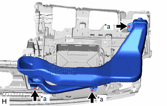
1. INSTALL LOWER NO. 2 INSTRUMENT PANEL FINISH PANEL
| (a) Install the lower No. 2 instrument panel finish panel with the 4 screws. |
|
.png)
2. INSTALL NO. 2 INSTRUMENT CLUSTER FINISH PANEL GARNISH
| (a) Attach the 2 clips to install the No. 2 instrument cluster finish panel garnish. |
|
(b) Install the 3 screws <A> or <B>.
3. INSTALL INSTRUMENT CLUSTER FINISH PANEL ASSEMBLY (w/ Headup Display)
| (a) Attach the 3 guides. |
|
.png)
(b) Attach the 2 claws and 3 clips to install the instrument cluster finish panel assembly.
4. INSTALL METER MIRROR SUB-ASSEMBLY (HEADUP DISPLAY) (w/ Headup Display)
Click here .gif)
5. INSTALL INSTRUMENT PANEL WIRE
(a) Attach the clamps to install the instrument panel wire.
.png)
6. INSTALL NAVIGATION ANTENNA ASSEMBLY WITH BRACKET
Click here
7. INSTALL INSTRUMENT PANEL PASSENGER WITHOUT DOOR AIRBAG ASSEMBLY
Click here
8. INSTALL NO. 2 INSTRUMENT PANEL WIRE
Click here
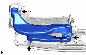
9. INSTALL NO. 2 INSTRUMENT PANEL CUSHION
NOTICE:
Installing the part with double-sided tape residue still remaining can cause poor adhesion. Therefore, using a cloth or other material, clean the part until the residue is completely removed (when reusing the upper instrument panel sub-assembly).
(a) Remove the peeling paper from a new No. 2 instrument panel cushion and press firmly to install the No. 2 instrument panel cushion in the position shown in the illustration.
.png)
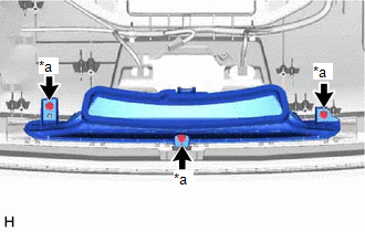
10. INSTALL NO. 1 INSTRUMENT PANEL CUSHION
NOTICE:
Installing the part with double-sided tape residue still remaining can cause poor adhesion. Therefore, using a cloth or other material, clean the part until the residue is completely removed (when reusing the upper instrument panel sub-assembly).
(a) Remove the peeling paper from a new No. 1 instrument panel cushion and press firmly to install the No. 1 instrument panel cushion in the position shown in the illustration.
.png)
11. INSTALL SIDE DEFROSTER NOZZLE LH
| (a) Attach the 4 claws to install the side defroster nozzle LH. |
|
.png)
12. INSTALL SIDE DEFROSTER NOZZLE RH
| (a) Attach the 4 claws to install the side defroster nozzle RH. |
|
.png)
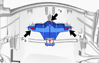
13. INSTALL NO. 2 DEFROSTER NOZZLE GARNISH
| (a) Attach the 6 claws to install the No. 2 defroster nozzle garnish. |
|
.png)
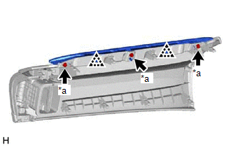
14. INSTALL NO. 1 DEFROSTER NOZZLE GARNISH
| (a) Attach the 6 claws to install the No. 1 defroster nozzle garnish. |
|
.png)
15. INSTALL METER HOOD SET BRACKET
| (a) Install the meter hood set bracket with the 3 screws <A> or <B>. |
|
(b) Attach the clamp.
16. INSTALL DEFROSTER NOZZLE ASSEMBLY
| (a) Install the defroster nozzle assembly with the 3 screws <A> or <B>. |
|
17. INSTALL NO. 1 HEATER TO REGISTER DUCT SUB-ASSEMBLY
| (a) Install the No. 1 heater to register duct sub-assembly with the 3 screws <A> or <B>. |
|
18. INSTALL NO. 2 HEATER TO REGISTER DUCT SUB-ASSEMBLY
| (a) Install the No. 2 heater to register duct sub-assembly with the 3 screws <A> or <B>. |
|
READ NEXT:
 Installation
INSTALLATION CAUTION / NOTICE / HINT HINT: A bolt without a torque specification is shown in the standard bolt chart. Click here PROCEDURE 1. INSTALL UPPER INSTRUMENT PANEL SUB-ASSEMBLY (a) Attach t
SEE MORE:
Random Access Memory (RAM) (P0604)
MONITOR DESCRIPTION The ECM continuously monitors its internal memory status. This self-check ensures that the ECM is functioning properly. The ECM memory status is diagnosed by internal mirroring of the main CPU and sub CPU to detect Random Access Memory (RAM) errors. If outputs from these CPUs are
GVIF Disconnected (from Extension Module to H/U) (B153A)
DESCRIPTION DTC No. Detection Item DTC Detection Condition Trouble Area B153A GVIF Disconnected (from Extension Module to H/U) GVIF disconnected (from navigation ECU to radio receiver assembly)
Navigation ECU
Radio receiver assembly
WIRING DIAGRAM CAUTION / NOTICE / HI
