Lexus NX: Refrigerant Line
Components
COMPONENTS
ILLUSTRATION
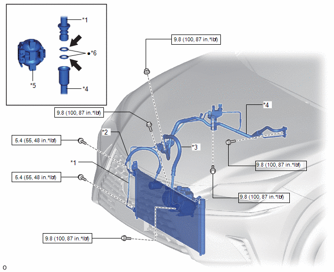
| *1 | LIQUID TUBE SUB-ASSEMBLY | *2 | DISCHARGE HOSE SUB-ASSEMBLY |
| *3 | SUCTION HOSE SUB-ASSEMBLY | *4 | AIR CONDITIONER TUBE AND ACCESSORY ASSEMBLY |
| *5 | PIPING CLAMP | *6 | O-RING |
.png) | N*m (kgf*cm, ft.*lbf): Specified torque | ● | Non-reusable part |
.png) | Compressor oil ND-OIL 11 or equivalent | - | - |
Removal
REMOVAL
PROCEDURE
1. RECOVER REFRIGERANT FROM REFRIGERATION SYSTEM
Click here .gif)
2. REMOVE PIPING CLAMP
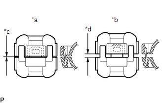
| (a) Install SST to the piping clamp as shown in the illustration. SST: 09870-00025 |
|
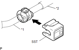
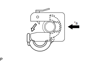
| (b) Hold the air conditioner tube and accessory assembly and liquid tube sub-assembly with each hand and push in SST with both thumbs. NOTICE: Do not apply excessive force to the air conditioner tube and accessory assembly or liquid tube sub-assembly as they may bend. |
|
| (c) Raise the stopper of SST and remove SST and the piping clamp together from the air conditioner tube and accessory assembly. |
|
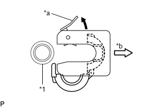
(d) Remove the piping clamp from SST.
(e) Remove the air conditioner tube and accessory assembly from the liquid tube sub-assembly.
(f) Remove the 2 O-rings from the liquid tube sub-assembly.
NOTICE:
Seal the openings of the disconnected parts using vinyl tape to prevent entry of moisture and foreign matter.
Installation
INSTALLATION
PROCEDURE
1. INSTALL PIPING CLAMP
(a) Remove the vinyl tape from the air conditioner tube and accessory assembly and liquid tube sub-assembly.
(b) Sufficiently apply compressor oil to 2 new O-rings and the fitting surfaces of the liquid tube sub-assembly.
Compressor Oil:
ND-OIL 11 or equivalent
(c) Install the 2 O-rings to the liquid tube sub-assembly.
(d) Install the air conditioner tube and accessory assembly to the liquid tube sub-assembly.
| (e) Install the piping clamp to the air conditioner tube and accessory assembly. NOTICE: Make sure that the piping clamp is engaged securely with no gap. |
|
2. CHARGE AIR CONDITIONING SYSTEM WITH REFRIGERANT
Click here .gif)
3. WARM UP COMPRESSOR
Click here
4. INSPECT FOR REFRIGERANT LEAK
Click here
READ NEXT:
 Relay
Relay
On-vehicle InspectionON-VEHICLE INSPECTION PROCEDURE 1. INSPECT PTC HEATER RELAY(PTC HTR NO. 1, NO. 3) (a) Measure the resistance according to the value(s) in the table below. Standard Resistance:
Components
COMPONENTS ILLUSTRATION *1 CONSOLE ARMREST ASSEMBLY *2 COOLER THERMISTOR (ROOM TEMPERATURE SENSOR) *3 COWL SIDE TRIM BOARD LH *4 DOOR SCUFF PLATE ASSEMBLY LH *5 INSTRUMENT SI
SEE MORE:
Communication Malfunction between ECUs Connected by LIN (B2785)
DESCRIPTION The certification ECU intermittently monitors the LIN communication bus between the components related to certification. DTC B2785 is stored when a malfunction in the LIN communication bus between the components related to certification is detected 3 times consecutively. DTC No. Det
Inspection
INSPECTION PROCEDURE 1. INSPECT SERVICE PLUG GRIP (a) Measure the resistance according to the value(s) in the table below. Standard Resistance: Tester Connection Condition Specified Condition Service plug grip Always Below 1 Ω If the result is not as specified, replace the ser
