Lexus NX: Relay
On-vehicle Inspection
ON-VEHICLE INSPECTION
PROCEDURE
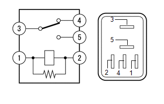
1. INSPECT NO. 1 MIRROR RELAY
(a) Remove the No. 1 mirror relay.
| (b) Measure the resistance according to the value(s) in the table below. Standard Resistance:
|
|
2. INSPECT NO. 2 MIRROR RELAY
(a) Remove the No. 2 mirror relay.
| (b) Measure the resistance according to the value(s) in the table below. Standard Resistance:
|
|
READ NEXT:
 Components
COMPONENTS ILLUSTRATION *1 DECK FLOOR BOX LH *2 NO. 3 DECK BOARD SUB-ASSEMBLY *3 REAR DECK FLOOR BOX *4 NEGATIVE AUXILIARY BATTERY TERMINAL N*m (kgf*cm, ft.*lbf): Specified
SEE MORE:
Installation
INSTALLATION CAUTION / NOTICE / HINT HINT:
Use the same procedure for the RH and LH sides.
The following procedure is for the LH side.
NOTICE: When the brake pedal is first depressed after replacing the brake pads or pushing back the disc brake piston, DTC C1214 may be output. As there is no
Installation
INSTALLATION PROCEDURE 1. INSTALL INTEGRATION CONTROL AND PANEL ASSEMBLY (VSC OFF SWITCH) (a) Install the integration control and panel assembly (VSC OFF switch) to the upper rear console panel sub-assembly with the 2 screws. HINT: The locations labeled A in the illustration are tightened togethe
