Lexus NX: Removal
REMOVAL
PROCEDURE
1. PRECAUTION
Click here .gif)
2. CHECK FOR DTC
(a) Check for DTCs.
Click here
NOTICE:
Confirm that P0AA6 (Hybrid Battery Voltage System Isolation Fault) is not output before removing or installing an HV battery module. If this DTC is output, perform troubleshooting for this DTC first.
3. REMOVE TONNEAU COVER ASSEMBLY
Click here
4. REMOVE DECK BOARD ASSEMBLY
Click here
5. REMOVE NO. 3 DECK BOARD SUB-ASSEMBLY
Click here
6. REMOVE DECK FLOOR BOX LH
Click here
7. DISCONNECT CABLE FROM NEGATIVE AUXILIARY BATTERY TERMINAL
Click here
8. REMOVE BATTERY SERVICE HOLE COVER
Click here
9. REMOVE HYBRID BATTERY SERVICE PLUG COVER
Click here
10. REMOVE SERVICE PLUG GRIP
Click here
11. DISCONNECT WIRE HARNESS
Click here
12. DISCONNECT INVERTER RESERVE TANK ASSEMBLY
Click here
13. REMOVE CONNECTOR COVER ASSEMBLY
Click here
14. CHECK TERMINAL VOLTAGE
Click here
15. INSTALL CONNECTOR COVER ASSEMBLY
Click here
16. REMOVE SEATBACK ASSEMBLY RH
for Manual Seat: Click here
for Power Seat: Click here
17. REMOVE REAR DECK FLOOR BOX
Click here
18. REMOVE NO. 2 DECK BOARD SUB-ASSEMBLY
Click here
19. REMOVE DECK FLOOR BOX RH
Click here
20. REMOVE NO. 1 TOOL BOX SUB-ASSEMBLY
Click here
21. REMOVE NO. 2 TOOL BOX SUB-ASSEMBLY
Click here
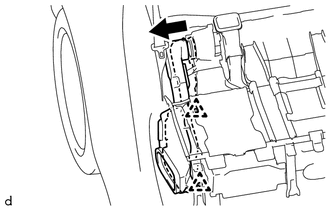
22. DISCONNECT NO. 2 HYBRID BATTERY INTAKE DUCT
CAUTION:
Wear insulated gloves.
| (a) Remove the 2 clips and disconnect the No. 2 hybrid battery intake duct. |
|
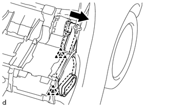
23. DISCONNECT NO. 1 HYBRID BATTERY INTAKE DUCT
CAUTION:
Wear insulated gloves.
| (a) Remove the 2 clips and disconnect the No. 1 hybrid battery intake duct. |
|
24. REMOVE NO. 4 HYBRID BATTERY EXHAUST DUCT
(a) Remove the No. 4 hybrid battery exhaust duct from the No. 2 hybrid battery exhaust duct.
25. REMOVE NO. 3 HYBRID BATTERY EXHAUST DUCT
(a) Remove the No. 3 hybrid battery exhaust duct from the No. 1 hybrid battery exhaust duct.
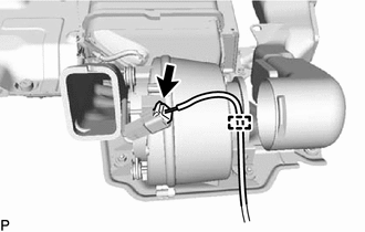
26. REMOVE BATTERY COOLING BLOWER ASSEMBLY LH
CAUTION:
Wear insulated gloves and use insulated tools.
| (a) Disconnect the connector and wire harness clamp from the battery cooling blower assembly LH. |
|
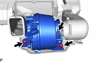
| (b) Remove the 3 nuts and battery cooling blower assembly LH. |
|
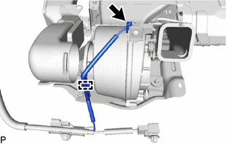
27. REMOVE BATTERY COOLING BLOWER ASSEMBLY RH
CAUTION:
Wear insulated gloves and use insulated tools.
| (a) Disconnect the connector and wire harness clamp from the battery cooling blower assembly RH. |
|
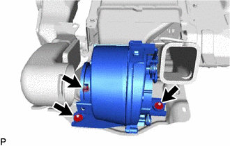
| (b) Remove the 3 nuts and battery cooling blower assembly RH. |
|
READ NEXT:
 Installation
INSTALLATION PROCEDURE 1. INSTALL BATTERY COOLING BLOWER ASSEMBLY LH CAUTION: Wear insulated gloves and use insulated tools. (a) Install the battery cooling blower assembly LH with the 3 nuts. Torque:
Components
COMPONENTS ILLUSTRATION *A for Manual Seat *B for Power Seat *1 NO. 2 BATTERY SERVICE COVER BOARD *2 NO. 3 BATTERY SERVICE COVER BOARD *3 REAR DOOR SCUFF PLATE LH *4 REAR
SEE MORE:
Black Screen
PROCEDURE 1. CHECK DISPLAY SETTING (a) Check that the display is not in screen off mode. OK: The display setting is not in screen off mode. NG CHANGE SCREEN TO SCREEN ON MODE
OK 2. CHECK IMAGE QUALITY SETTING (a) Check that the display settings (contrast,
Inspection
INSPECTION PROCEDURE 1. INSPECT TRIP SWITCH *1 ODO TRIP Switch *a Component without harness connected (Trip Switch) (a) Check the resistance. Measure the resistance according to the value(s) in the table below. Standard Resistance: Tester Connection Switch Condition Specified
