Lexus NX: Removal
REMOVAL
PROCEDURE
1. DISCHARGE FUEL SYSTEM PRESSURE
Click here .gif)
2. PRECAUTION
NOTICE:
After turning the power switch off, waiting time may be required before disconnecting the cable from the auxiliary battery negative (-) terminal.
Click here
3. REMOVE NO. 3 DECK BOARD SUB-ASSEMBLY
Click here
4. REMOVE REAR DECK FLOOR BOX
Click here
5. REMOVE DECK FLOOR BOX LH
Click here
6. DISCONNECT CABLE FROM NEGATIVE AUXILIARY BATTERY TERMINAL
7. REMOVE THROTTLE WITH MOTOR BODY ASSEMBLY
Click here
8. REMOVE WINDSHIELD WIPER MOTOR ASSEMBLY
Click here
9. REMOVE SUSPENSION TOWER DAMPER
-
w/ Performance Damper:
Click here
-
w/o Performance Damper:
Click here
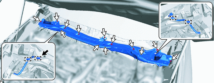
10. REMOVE OUTER COWL TOP PANEL
(a) Disconnect the connector.
(b) Detach the 4 clamps and disconnect the wire harness.
(c) Remove the 13 bolts and outer cowl top panel.
.png) | Connector | .png) | Bolt |
11. REMOVE AIR CLEANER FILTER ELEMENT SUB-ASSEMBLY
Click here
12. REMOVE AIR CLEANER CASE SUB-ASSEMBLY
Click here
13. REMOVE EGR VALVE ASSEMBLY
Click here
14. REMOVE MANIFOLD ABSOLUTE PRESSURE SENSOR
Click here
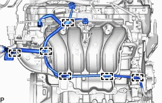
15. DISCONNECT ENGINE WIRE
| (a) Disconnect the heated oxygen sensor connector. |
|
| (b) Detach the 6 clamps and disconnect the engine wire. |
|
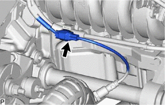
16. DISCONNECT INTAKE MANIFOLD
| (a) Slide the clamp and disconnect the No. 2 PCV hose from the intake manifold. |
|
.png)
| (b) Remove the 6 bolts and disconnect the intake manifold. |
|
.png)
17. DISCONNECT NO. 1 EGR PIPE
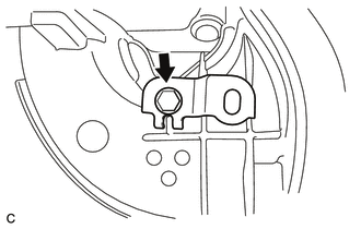
| (a) Remove the nut and bolt, and then disconnect the No. 1 EGR pipe from the EGR cooler assembly. |
|
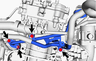
(b) Remove the 2 bolts and disconnect the No. 1 EGR pipe.
(c) Remove the gasket from the No. 1 EGR pipe.
18. DISCONNECT FUEL TUBE SUB-ASSEMBLY
Click here
19. REMOVE FUEL DELIVERY PIPE
Click here
20. REMOVE INTAKE MANIFOLD
(a) Remove the intake manifold from the vehicle.
| (b) Remove the No. 1 intake manifold to head gasket from the intake manifold. |
|
.png)
| (c) Remove the bolt and wiring harness clamp bracket. |
|
| (d) Remove the vacuum hose from the intake manifold. |
|
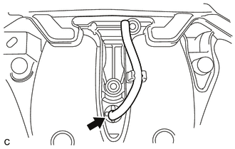
| (e) Slide the clamp and disconnect the purge line hose from the intake manifold. |
|
.png)
READ NEXT:
 Installation
INSTALLATION PROCEDURE 1. INSTALL INTAKE MANIFOLD (a) Connect the purge line hose to the intake manifold, and slide the clamp to secure the hose. HINT: Make sure the hose clamp is oriented as shown
Intake System
On-vehicle InspectionON-VEHICLE INSPECTION PROCEDURE 1. INSPECT INTAKE SYSTEM HINT: Perform "Inspection After Repair" after repairing air leaks in the intake system. Click here (a) Check that there
SEE MORE:
Reassembly
REASSEMBLY CAUTION / NOTICE / HINT NOTICE:
Handle components indoors as much as possible to prevent foreign matter from entering and adhering to headlight assembly components.
Do not reuse parts which have reduced fastening ability due to thread damage.
When installing components, make sure t
DC / DC Converter Status Circuit (P0A08-264)
DESCRIPTION The DC/DC converter converts the DC 244.8 V of the HV battery into DC 12 V in order to supply power to areas such as the vehicle's lighting, audio, and ECU systems. In addition, it charges the auxiliary battery. A transistor bridge circuit initially converts DC 244.8 V into alternating c
