Lexus NX: Removal
REMOVAL
CAUTION / NOTICE / HINT
NOTICE:
While the auxiliary battery is connected, even if the power switch is off, the brake control system activates when the brake pedal is depressed or any door courtesy switch turns on. Therefore, when servicing the brake system components, do not operate the brake pedal or open/close the doors while the auxiliary battery is connected.
PROCEDURE
1. PRECAUTION
NOTICE:
After turning the power switch is turned off, there may be a waiting time before disconnecting the auxiliary negative (-) battery terminal.
Click here .gif)
2. REMOVE NO. 3 DECK BOARD SUB-ASSEMBLY
Click here
3. REMOVE REAR DECK FLOOR BOX
Click here
4. REMOVE DECK FLOOR BOX LH
Click here
5. DISCONNECT CABLE FROM NEGATIVE AUXILIARY BATTERY TERMINAL
Click here
6. REMOVE DECK TRIM SIDE PANEL ASSEMBLY LH
Click here
7. REMOVE PARKING BRAKE ECU ASSEMBLY
Click here
8. REMOVE ABSORBER CONTROL ECU
| (a) Disconnect the 2 connectors from the absorber control ECU. |
|
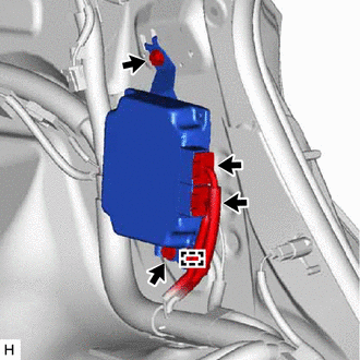
(b) Disconnect the clamp from the absorber control ECU.
(c) Remove the 2 bolts and absorber control ECU.
NOTICE:
- Avoid any impact to the absorber control ECU.
- Do not drop the absorber control ECU. If it is dropped, replace it with a new one.
READ NEXT:
 Installation
INSTALLATION PROCEDURE 1. INSTALL ABSORBER CONTROL ECU (a) Install the absorber control ECU with the 2 bolts. Torque: 8.5 N·m {87 kgf·cm, 75 in·lbf} NOTICE:
Avoid any impact to the absorber con
Tire And Wheel
RemovalREMOVAL PROCEDURE 1. REMOVE WHEEL ASSEMBLY (a) Loosen the axle hub nuts approximately 90°. (b) Lift up the vehicle and remove the axle hub nuts and wheel assembly. InstallationINSTALLATION P
SEE MORE:
Inspection
INSPECTION PROCEDURE 1. INSPECT FUEL PUMP ASSEMBLY WITH FILTER (a) Check the resistance. (1) Measure the resistance according to the value(s) in the table below. Standard Resistance: Tester Connection Condition Specified Condition 1 - 2 20°C (68°F) 0.2 to 3.0 Ω If the result
Terminals Of Ecu
TERMINALS OF ECU PARKING ASSIST ECU (a) Disconnect the P44 parking assist ECU connector. (b) Measure the voltage and resistance according to the value(s) in the table below. Terminal No. (Symbol) Wiring Color Terminal Description Condition Specified Condition P44-1 (+B) - P44-4 (GND1
