Lexus NX: Removal
REMOVAL
CAUTION / NOTICE / HINT
HINT:
- Use the same procedure for the RH and LH sides.
- The procedure listed below is for the LH side.
PROCEDURE
1. PRECAUTION
NOTICE:
After the power switch off is turned off, there may be a waiting time before disconnecting the auxiliary negative (-) battery terminal.
Click here .gif)
2. REMOVE NO. 3 DECK BOARD SUB-ASSEMBLY
Click here
3. REMOVE REAR DECK FLOOR BOX
Click here
4. REMOVE DECK FLOOR BOX LH
Click here
5. DISCONNECT CABLE FROM NEGATIVE AUXILIARY BATTERY TERMINAL
Click here
6. REMOVE FRONT DOOR TRIM COVER LH
Click here
7. REMOVE FRONT DOOR INSIDE HANDLE BEZEL PLUG LH
Click here
8. REMOVE POWER WINDOW REGULATOR MASTER SWITCH ASSEMBLY WITH FRONT DOOR ARMREST BASE PANEL
Click here
9. REMOVE FRONT DOOR TRIM BOARD SUB-ASSEMBLY LH
Click here
10. REMOVE FRONT DOOR INNER GLASS WEATHERSTRIP LH
Click here
11. REMOVE FRONT DOOR ARMREST SET BRACKET LH
Click here
12. REMOVE FRONT DOOR SERVICE HOLE COVER LH
Click here
13. REMOVE FRONT DOOR GLASS RUN LH
Click here
14. REMOVE FRONT DOOR GLASS SUB-ASSEMBLY LH
Click here
15. REMOVE FRONT DOOR BELT MOULDING ASSEMBLY LH
(a) Put protective tape around the front door belt moulding assembly LH.
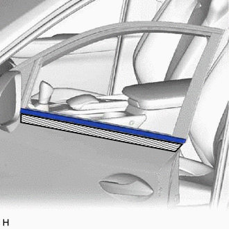
.png) | Protective Tape |
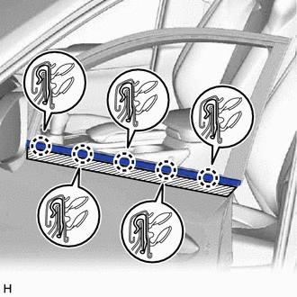
| (b) Using moulding remover D, detach the 5 claws and remove the front door belt moulding assembly LH. |
|
READ NEXT:
 Components
COMPONENTS ILLUSTRATION *1 FRONT DOOR LOWER OUTSIDE MOULDING SUB-ASSEMBLY LH *2 HOLE COVER ILLUSTRATION *1 FRONT DOOR UPPER OUTSIDE MOULDING PAD - - ● Non-reusable part
Removal
REMOVAL CAUTION / NOTICE / HINT HINT:
Use the same procedure for the RH and LH sides.
The procedures listed below are for the LH side.
PROCEDURE 1. REMOVE FRONT DOOR LOWER OUTSIDE MOULDING SUB
SEE MORE:
Removal
REMOVAL CAUTION / NOTICE / HINT NOTICE:
Do not replace the spiral cable with the battery connected and the power switch on (IG).
Do not rotate the spiral cable when the following conditions are met: 1) The steering wheel is removed, 2) the battery is connected, and 3) thepower switch on (IG).
Installation
INSTALLATION PROCEDURE 1. INSTALL NO. 1 AMPLIFIER ANTENNA ASSEMBLY (a) Attach the guide and install the No. 1 amplifier antenna assembly with the bolt. Torque: 8.3 N·m {85 kgf·cm, 73 in·lbf} (b) Connect the 2 connectors. 2. INSTALL BACK DOOR TRIM BOARD ASSEMBLY Click here 3. INSTALL BACK DOOR
