Lexus NX: Removal
REMOVAL
CAUTION / NOTICE / HINT
HINT:
- Use the same procedure for the RH and LH sides.
- The procedure listed below is for the LH side.
PROCEDURE
1. REMOVE REAR WIPER ARM HEAD CAP
Click here .gif)
2. REMOVE REAR WIPER ARM AND BLADE ASSEMBLY
Click here
3. REMOVE REAR WIPER MOTOR GROMMET
Click here
4. REMOVE BACK DOOR TRIM BASE (w/ Power Back Door)
Click here
5. REMOVE PULL HANDLE (w/ Power Back Door)
Click here
6. REMOVE BACK DOOR FINISH COVER LH (w/o Power Back Door)
Click here
7. REMOVE BACK DOOR FINISH COVER RH (w/o Power Back Door)
HINT:
Use the same procedure described for the LH side.
8. REMOVE BACK DOOR CENTER GARNISH
Click here
9. REMOVE BACK DOOR SIDE GARNISH LH
Click here
10. REMOVE BACK DOOR SIDE GARNISH RH
HINT:
Use the same procedure described for the LH side.
11. REMOVE BACK DOOR TRIM BOARD ASSEMBLY
Click here
12. REMOVE REAR SPOILER
Click here
13. REMOVE REAR SIDE SPOILER SUB-ASSEMBLY LH
Click here
14. REMOVE REAR SIDE SPOILER SUB-ASSEMBLY RH
HINT:
Use the same procedure described for the LH side.
15. REMOVE BACK DOOR OUTSIDE GARNISH SUB-ASSEMBLY
Click here
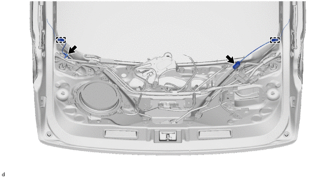
16. REMOVE BACK DOOR GLASS
(a) Disconnect the rear window defogger connector.
(b) Remove the bolt and ground wire.
(c) Detach the 2 clamps.
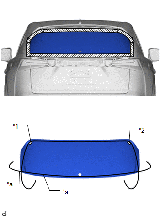
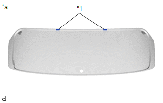
| *1 | No. 3 Window Glass Spacer |
| *2 | No. 4 Window Glass Spacer |
| *a | Piano Wire |
.png) | Protective Tape |
(d) Apply protective tape to the outer surface of the vehicle body to prevent scratches.
NOTICE:
When separating the back door glass from the vehicle, be careful not to damage the vehicle paint or interior/exterior ornaments.
(e) From the interior, insert a piano wire between the vehicle body and back door glass as shown in the illustration.
(f) Tie objects that can serve as handles (for example, wooden blocks) to both wire ends.
| (g) Place matchmarks over the glass and vehicle body at the locations indicated in the illustration. HINT: Matchmarks do not need to be placed if the glass is not going to be reused. |
|
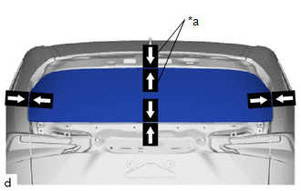
(h) Cut through the adhesive by pulling the piano wire around the back door glass.
NOTICE:
Leave as much adhesive on the vehicle body as possible when removing the back door glass.
(i) Using suction cups, remove the back door glass.
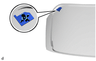
17. REMOVE BACK WINDOW OUTSIDE MOULDING
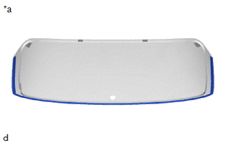
| *a | Back Side |
(a) When reusing the back door glass:
(1) Using a scraper, remove the back window outside moulding.
NOTICE:
- Be careful not to damage the back door glass.
- Be sure to replace the back window outside moulding with a new one.
18. REMOVE BACK DOOR GLASS SPACER
(a) When reusing the back door glass:
| (1) Using a scraper, remove the back door glass spacer. NOTICE:
|
|
19. REMOVE NO. 3 BACK WINDOW GLASS SPACER
(a) When reusing the back door glass:
| (1) Using a scraper, remove the No. 3 back window glass spacer. NOTICE:
|
|
20. REMOVE NO. 4 BACK WINDOW GLASS SPACER
HINT:
Use the same procedure described for the No. 3 back window glass spacer.
READ NEXT:
 Installation
INSTALLATION CAUTION / NOTICE / HINT NOTICE: Make sure to use Toyota Genuine Windshield Glass Adhesive (High Modulus Type) or an equivalent high modulus adhesive. HINT:
Use the same procedure for t
Front Passenger Side Power Window Switch
ComponentsCOMPONENTS ILLUSTRATION *1 POWER WINDOW REGULATOR SWITCH ASSEMBLY *2 POWER WINDOW REGULATOR SWITCH ASSEMBLY WITH FRONT DOOR ARMREST BASE PANEL *3 FRONT DOOR ARMREST BASE PAN
SEE MORE:
Rear Power Window RH Auto Up / Down Function does not Operate with Rear Power Window Switch RH
DESCRIPTION If the manual up and down function operates normally but the auto up and down function does not, then fail-safe mode may be functioning. If power window initialization has not been performed, the auto up and down function will not operate. Click here WIRING DIAGRAM CAUTION / NOTICE /
Brake System (P1578)
DESCRIPTION When a malfunction in the electronically controlled brake system is detected, DTC P1578 is stored. DTC No. Detection Item DTC Detection Condition Trouble Area DTC Output from P1578 Brake System When the power switch is on (IG) and the dynamic radar cruise control syste
