Lexus NX: Removal
REMOVAL
CAUTION / NOTICE / HINT
NOTICE:
When replacing the combination meter assembly, make sure to replace it with a new one.
PROCEDURE
1. DISABLE AUTOAWAY/RETURN FUNCTION (for Power Tilt and Power Telescopic Steering Column)
(a) Disable the autoaway/return function by changing the customize parameter.
Click here .gif)
CAUTION:
Record the current customize parameter setting (whether the autoaway/return function is enabled or disabled) in order to restore the current setting after finishing the operation.
HINT:
Performing the above operation causes the autoaway/return function to be disabled when the power switch is turned off.
(b) Turn the power switch on (IG). Operate the tilt and telescopic switch to fully extend and lower the steering column assembly.
(c) Turn the power switch off.
2. REMOVE CONSOLE ARMREST ASSEMBLY
Click here
3. REMOVE UPPER REAR CONSOLE PANEL
Click here
4. REMOVE UPPER NO. 2 CONSOLE PANEL GARNISH
Click here
5. REMOVE UPPER NO. 1 CONSOLE PANEL GARNISH
Click here
6. REMOVE INSTRUMENT SIDE PANEL LH
Click here
7. REMOVE NO. 1 INSTRUMENT PANEL SAFETY PAD SUB-ASSEMBLY
Click here
8. REMOVE NO. 1 INSTRUMENT PANEL UNDER COVER SUB-ASSEMBLY
Click here
9. REMOVE LOWER NO. 1 INSTRUMENT PANEL FINISH PANEL
Click here
10. REMOVE NO. 1 SWITCH HOLE BASE
Click here
11. REMOVE INSTRUMENT SIDE PANEL RH
Click here
12. REMOVE NO. 2 INSTRUMENT PANEL SAFETY PAD SUB-ASSEMBLY
Click here
13. REMOVE INSTRUMENT PANEL FINISH PLATE
Click here
14. REMOVE MULTI-DISPLAY ASSEMBLY WITH BRACKET
Click here
15. REMOVE CENTER INSTRUMENT CLUSTER FINISH PANEL ASSEMBLY
Click here
16. REMOVE INSTRUMENT CLUSTER FINISH PANEL SUB-ASSEMBLY
Click here
17. REMOVE COMBINATION METER ASSEMBLY
| (a) Remove the 4 screws. |
|
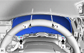
(b) Disconnect the connectors, detach the clamp and remove the combination meter assembly.
READ NEXT:
 Disassembly
DISASSEMBLY CAUTION / NOTICE / HINT NOTICE: Do not allow any dirt (fingerprints, grease, etc.) to adhere to the meter glass. If the glass is dirty, wipe it clean with a soft cloth. PROCEDURE 1. REMOVE
Reassembly
REASSEMBLY CAUTION / NOTICE / HINT NOTICE: Do not allow any dirt (fingerprints, grease, etc.) to adhere to the meter glass. If the glass is dirty, wipe it clean with a soft cloth. PROCEDURE 1. INSTALL
Installation
INSTALLATION CAUTION / NOTICE / HINT NOTICE: When replacing the combination meter assembly, make sure to replace it with a new one. PROCEDURE 1. INSTALL COMBINATION METER ASSEMBLY (a) Connect the c
SEE MORE:
Evaporative Emission Control System Pressure Sensor Range / Performance (P0451-P0453)
DTC SUMMARY DTC No. Detection Item DTC Detection Condition Trouble Area MIL Memory P0451 Evaporative Emission Control System Pressure Sensor Range / Performance Sensor output voltage fluctuates frequently in a certain time period.
Canister pump module
Connector/wire harne
Removal
REMOVAL PROCEDURE 1. RECOVER REFRIGERANT FROM REFRIGERATION SYSTEM Click here 2. REMOVE BATTERY SERVICE HOLE COVER Click here 3. REMOVE HYBRID BATTERY SERVICE PLUG COVER Click here 4. REMOVE SERVICE PLUG GRIP Click here 5. CHECK TERMINAL VOLTAGE Click here 6. REMOVE NO. 1 ENGINE UNDER
