Lexus NX: Removal
REMOVAL
PROCEDURE
1. DISABLE AUTOAWAY/RETURN FUNCTION (for Power Tilt and Power Telescopic Steering Column)
(a) Disable the autoaway/return function by changing the customize parameter.
Click here .gif)
CAUTION:
Record the current customize parameter setting (whether the autoaway/return function is enabled or disabled) in order to restore the current setting after finishing the operation.
HINT:
Performing the above operation causes the autoaway/return function to be disabled when the power switch is turned off.
(b) Turn the power switch on (IG). Operate the tilt and telescopic switch to fully extend and lower the steering column assembly.
(c) Turn the power switch off.
2. REMOVE NO. 3 DECK BOARD SUB-ASSEMBLY
Click here
3. REMOVE REAR DECK FLOOR BOX
Click here
4. REMOVE DECK FLOOR BOX LH
Click here
5. PRECAUTION
CAUTION:
Be sure to read Precoution thoroughly before serving.
Click here
NOTICE:
After turning the power switch off, there may be a waiting time before disconnecting the negative (-) auxiliary battery terminal.
Click here
6. DISCONNECT CABLE FROM NEGATIVE AUXILIARY BATTERY TERMINAL
CAUTION:
- Wait at least 90 seconds after disconnecting the cable from the negative (-) auxiliary battery terminal to disable the SRS system.
- If the airbag deploys for any reason. it may cause a serious accident.
7. REMOVE UPPER INSTRUMENT PANEL SUB-ASSEMBLY
Click here
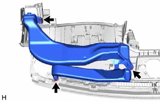
8. REMOVE NO. 1 HEATER TO REGISTER DUCT SUB-ASSEMBLY
| (a) Remove the 3 screws and No. 1 heater to register duct sub-assembly. |
|
9. REMOVE METER MIRROR SUB-ASSEMBLY (HEADUP DISPLAY)
| (a) Disconnect the connector. |
|
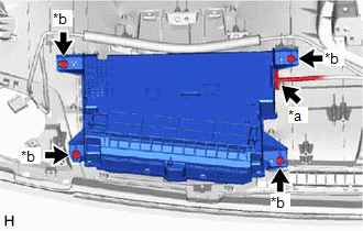
(b) Remove the 4 screws and meter mirror sub-assembly (headup display).
READ NEXT:
 Disassembly
DISASSEMBLY PROCEDURE 1. REMOVE NO. 1 COMBINATION METER MIRROR PLATE (a) Detach the 10 claws and remove the No. 1 combination meter mirror plate from the meter mirror sub-assembly (headup display).
Reassembly
REASSEMBLY PROCEDURE 1. INSTALL NO. 1 COMBINATION METER MIRROR PLATE (a) Attach the 10 claws to install the No. 1 combination meter mirror plate to the meter mirror sub-assembly (headup display).
Installation
INSTALLATION PROCEDURE 1. INSTALL METER MIRROR SUB-ASSEMBLY (HEADUP DISPLAY) (a) Install the meter mirror sub-assembly (headup display) with the 4 screws. *a Screw *b Connector
SEE MORE:
Luggage Compartment Room Light
ComponentsCOMPONENTS ILLUSTRATION *1 NO. 1 LUGGAGE COMPARTMENT LIGHT ASSEMBLY - - RemovalREMOVAL PROCEDURE 1. REMOVE NO. 1 LUGGAGE COMPARTMENT LIGHT ASSEMBLY (for LH Side) (a) Put protective tape around the No. 1 luggage compartment light assembly. Protective Tape (b) Using
DC / DC Converter Status Circuit Low Input (P0A09-591)
DESCRIPTION The DC/DC converter varies output voltage based on voltage change signals (VLO signal line) received from the hybrid vehicle control ECU. If the vehicle is being driven with an inoperative DC/DC converter, the voltage of the auxiliary battery will drop, which will prevent the continued o
