Lexus NX: Removal
REMOVAL
PROCEDURE
1. REMOVE DECK BOARD ASSEMBLY
Click here .gif)
2. REMOVE NO. 3 DECK BOARD SUB-ASSEMBLY
Click here
3. REMOVE REAR DECK FLOOR BOX
Click here
4. REMOVE DECK FLOOR BOX LH
Click here
5. PRECAUTION
CAUTION:
Be sure to read Precaution thoroughly before serving.
Click here
NOTICE:
After turning the power switch off, there may be a waiting time before disconnecting the negative (-) auxiliary battery terminal.
Click here
6. DISCONNECT CABLE FROM NEGATIVE AUXILIARY BATTERY TERMINAL
CAUTION:
- Wait at least 90 seconds after disconnecting the cable from the negative (-) auxiliary battery terminal to disable the SRS system.
- If the airbag deploys for any reason. it may cause a serious accident.
7. REMOVE INSTRUMENT PANEL FINISH PLATE
Click here
8. REMOVE MULTI-DISPLAY ASSEMBLY WITH BRACKET
Click here
9. REMOVE CONSOLE ARMREST ASSEMBLY
Click here
10. REMOVE UPPER REAR CONSOLE PANEL
Click here
11. REMOVE UPPER NO. 1 CONSOLE PANEL GARNISH
Click here
12. REMOVE UPPER NO. 2 CONSOLE PANEL GARNISH
Click here
13. REMOVE INSTRUMENT SIDE PANEL RH
Click here
14. REMOVE INSTRUMENT SIDE PANEL LH
Click here
15. REMOVE NO. 1 INSTRUMENT PANEL SAFETY PAD SUB-ASSEMBLY
Click here
16. REMOVE NO. 1 INSTRUMENT PANEL UNDER COVER SUB-ASSEMBLY
Click here
17. REMOVE LOWER NO. 1 INSTRUMENT PANEL FINISH PANEL
Click here
18. REMOVE NO. 1 SWITCH HOLE BASE
Click here
19. REMOVE NO. 2 INSTRUMENT PANEL SAFETY PAD SUB-ASSEMBLY
Click here
20. REMOVE CENTER INSTRUMENT CLUSTER FINISH PANEL ASSEMBLY
Click here
21. REMOVE SHIFT LEVER KNOB SUB-ASSEMBLY
Click here
22. REMOVE UPPER REAR CONSOLE PANEL SUB-ASSEMBLY
Click here
23. REMOVE AIR CONDITIONING CONTROL ASSEMBLY
Click here
24. REMOVE RADIO RECEIVER ASSEMBLY WITH BRACKET
| (a) Remove the 2 bolts. |
|
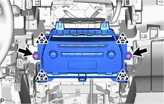
(b) Pull the radio receiver assembly with bracket toward the rear of the vehicle and disengage the 4 clips.
(c) Disconnect each connector and remove the radio receiver assembly with bracket.
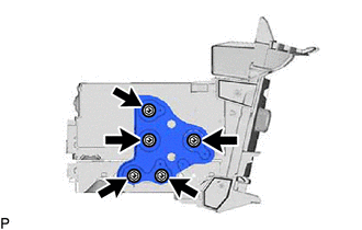
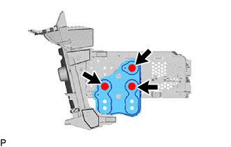
25. REMOVE NO. 1 RADIO BRACKET
| (a) w/ Navigation System (1) Remove the 5 screws and No. 1 radio bracket. |
|
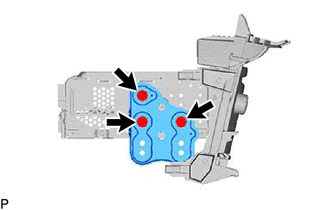
| (b) w/o Navigation System (1) Remove the 3 screws and No. 1 radio bracket. |
|
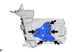
26. REMOVE NO. 2 RADIO BRACKET
| (a) w/ Navigation System (1) Remove the 5 screws and No. 2 radio bracket. |
|
| (b) w/ Navigation System (1) Remove the 3 screws and No. 2 radio bracket. |
|
27. REMOVE NAVIGATION ECU
Click here
28. REMOVE RADIO RECEIVER ASSEMBLY
READ NEXT:
 Installation
INSTALLATION PROCEDURE 1. INSTALL RADIO RECEIVER ASSEMBLY 2. INSTALL NAVIGATION ECU Click here 3. INSTALL NO. 1 RADIO BRACKET (a) w/ Navigation System (1) Install the No. 1 radio bracket with the 5
Components
COMPONENTS ILLUSTRATION *A for 8 Speakers *B for 10 Speakers *C for 14 Speakers - - *1 REAR DOOR INSIDE HANDLE BEZEL PLUG LH *2 REAR DOOR TRIM BOARD SUB-ASSEMBLY LH *
SEE MORE:
Installation
INSTALLATION CAUTION / NOTICE / HINT PROCEDURE 1. INSTALL QUARTER OUTSIDE MOULDING SUB-ASSEMBLY LH HINT: When installing the quarter outside moulding sub-assembly LH, heat the vehicle body and quarter outside moulding sub-assembly LH using a heat light. Standard: Item Temperature Vehicle B
Components
COMPONENTS ILLUSTRATION *1 RAIN SENSOR *2 RAIN SENSOR COVER *3 RAIN SENSOR TAPE - -
