Lexus NX: Removal
REMOVAL
PROCEDURE
1. REMOVE REAR SEAT ASSEMBLY
(a) for Power Seat:
Click here .gif)
(b) for Manual Seat:
Click here
2. REMOVE REAR FLOOR FINISH PLATE
Click here
3. REMOVE REAR DOOR OPENING TRIM WEATHERSTRIP LH
Click here
4. REMOVE UPPER DECK TRIM SIDE BOARD LH
Click here
5. REMOVE ROPE HOOK ASSEMBLY
Click here
6. REMOVE LUGGAGE HOLD BELT STRIKER ASSEMBLY
Click here
7. REMOVE NO. 1 LUGGAGE COMPARTMENT TRIM HOOK
Click here
8. REMOVE DECK TRIM SIDE PANEL ASSEMBLY LH
Click here
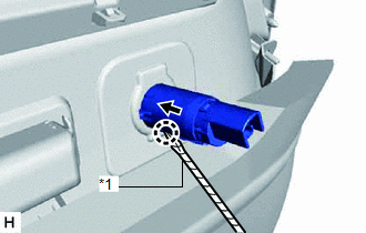
9. REMOVE REAR NO. 1 POWER OUTLET SOCKET ASSEMBLY
| (a) Using a screwdriver, detach the claw to remove the rear No. 1 power outlet socket assembly. HINT:
|
|
10. REMOVE REAR POWER OUTLET SOCKET COVER
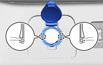
(a) Detach the 2 claws and remove the rear power outlet socket cover.
HINT:
Use the same procedure to remove the other power outlet socket cover.
READ NEXT:
 Installation
INSTALLATION PROCEDURE 1. INSTALL REAR POWER OUTLET SOCKET COVER (a) Attach the 2 claws to install the rear power outlet socket cover. HINT: Use the same procedure to install the other power outlet so
Power Point Socket(for Console Box)
ComponentsCOMPONENTS ILLUSTRATION *1 NO. 1 POWER OUTLET SOCKET ASSEMBLY *2 NO. 1 POWER OUTLET SOCKET COVER *3 NO. 3 BOX PANEL - - RemovalREMOVAL PROCEDURE 1. REMOVE NO. 3 BOX
Relay
On-vehicle InspectionON-VEHICLE INSPECTION PROCEDURE 1. INSPECT POWER OUTLET SOCKET RELAY (a) Remove the power outlet socket relay. (b) Measure the resistance according to the value(s)
SEE MORE:
Parts Location
PARTS LOCATION ILLUSTRATION *1 COMBINATION METER ASSEMBLY *2 CLIMATE CONTROL SWITCH (for Driver Side) *3 CLIMATE CONTROL SWITCH (for Front Passenger Side) *4 AIR CONDITIONING CONTROL ASSEMBLY *5 AIR CONDITIONING AMPLIFIER ASSEMBLY *6 DLC3 *7 INSTRUMENT PANEL JUNCT
Power Source Circuit
DESCRIPTION The main body ECU (multiplex network body ECU) receives IG signals and supplies power to the headlight ECU sub-assembly via the H-LP relay. WIRING DIAGRAM CAUTION / NOTICE / HINT NOTICE:
The lighting system (for Triple Beam Headlight) uses the LIN communication system and CAN communi
