Lexus NX: Removal
REMOVAL
CAUTION / NOTICE / HINT
CAUTION:
Wear protective gloves. Sharp areas on the parts may injure your hands.
PROCEDURE
1. REMOVE FRONT SEAT ASSEMBLY LH
Click here .gif)
2. REMOVE FRONT LOWER SEAT CUSHION SHIELD
Click here
3. REMOVE FRONT SEAT CUSHION SHIELD LH
Click here
4. REMOVE FRONT INNER SEAT CUSHION SHIELD LH
Click here
5. REMOVE FRONT SEAT HEADREST SUPPORT
Click here
6. REMOVE SEPARATE TYPE FRONT SEATBACK COVER WITH PAD
(a) w/ Seat Heater System:
| (1) Disconnect the connector. |
|
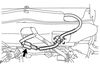
(2) Detach the clamp to disconnect the seat heater wire harness.
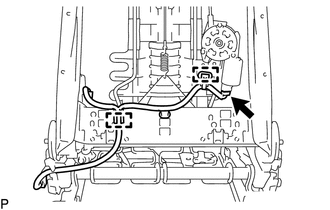
| (b) Remove the 2 nuts to disconnect the 3 seatback cover brackets. |
|
.png)
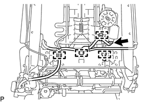
| (c) w/ Climate Control Seat System: (1) Detach the 2 claws to disconnect the duct of the seatback climate control blower. |
|
.png)
(d) Remove the separate type front seatback cover with pad.
7. REMOVE SEATBACK FELT
Click here
8. REMOVE FRONT NO. 1 SEATBACK HOOK
Click here
9. REMOVE FRONT SEATBACK EDGE PROTECTOR
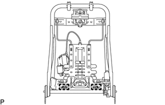
| (a) w/ Climate Control Seat System: (1) Disconnect the connector. (2) Detach the 4 clamps to disconnect the front No. 2 seat wire LH. |
|
| (b) w/o Climate Control Seat System: (1) Disconnect the connector. (2) Detach the 2 clamps to disconnect the front No. 2 seat wire LH. |
|
| (c) Detach the 2 claws and 4 guides to remove the 2 front seatback edge protectors. |
|
.png)
10. REMOVE LUMBAR SUPPORT ADJUSTER ASSEMBLY LH
| (a) Detach the 2 hooks to remove the lumbar support adjuster assembly LH from the front seatback frame sub-assembly LH. |
|
READ NEXT:
 Inspection
INSPECTION PROCEDURE 1. INSPECT LUMBAR SUPPORT ADJUSTER ASSEMBLY LH (a) Check the operation of the lumbar support adjuster assembly LH. (1) Apply auxiliary battery voltage to the lumbar support adj
Installation
INSTALLATION CAUTION / NOTICE / HINT CAUTION: Wear protective gloves. Sharp areas on the parts may injure your hands. PROCEDURE 1. INSTALL LUMBAR SUPPORT ADJUSTER ASSEMBLY LH (a) Attach the 2 hooks to
SEE MORE:
Low Output Signal of Front Speed Sensor RH (C1271,C1272,C1464,C1465)
DESCRIPTION Each speed sensor detects the wheel speed and sends the signals to the skid control ECU (brake booster with master cylinder assembly). These signals are used for ABS control. DTCs C1271 and C1272 are cleared when the speed sensor sends a wheel speed signal or when Test Mode ends. DTCs C1
Components
COMPONENTS ILLUSTRATION *1 COLUMN HOLE COVER SILENCER SHEET *2 COMBINATION SWITCH ASSEMBLY WITH SPIRAL CABLE SUB-ASSEMBLY *3 ELECTRIC POWER STEERING COLUMN SUB-ASSEMBLY *4 LOWER STEERING COLUMN COVER *5 NO. 1 AIR DUCT *6 NO. 2 STEERING INTERMEDIATE SHAFT ASSEMBLY *7
