Lexus NX: Removal
REMOVAL
PROCEDURE
1. REMOVE CONSOLE ARMREST ASSEMBLY (for Front Side)
Click here .gif)
2. REMOVE UPPER NO. 2 CONSOLE PANEL GARNISH (for Front Side)
Click here
3. REMOVE DOOR SCUFF PLATE ASSEMBLY LH (for Front Side)
Click here
4. REMOVE COWL SIDE TRIM BOARD LH (for Front Side)
Click here
5. REMOVE INSTRUMENT SIDE PANEL LH (for Front Side)
Click here
6. REMOVE NO. 1 INSTRUMENT PANEL SAFETY PAD SUB-ASSEMBLY (for Front Side)
Click here
7. REMOVE NO. 1 INSTRUMENT PANEL UNDER COVER SUB-ASSEMBLY (for Front Side)
Click here
8. REMOVE LOWER NO. 1 INSTRUMENT PANEL FINISH PANEL (for Front Side)
Click here
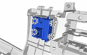
9. REMOVE NO. 1 FOLD SEAT SWITCH ASSEMBLY (for Front Side)
| (a) Detach the 4 claws to remove the No. 1 fold seat switch assembly. |
|
10. REMOVE BENCH TYPE REAR SEAT CUSHION ASSEMBLY (for Rear Seat)
Click here
11. REMOVE NO. 3 BATTERY SERVICE COVER BOARD (for Rear Seat)
Click here
12. REMOVE NO. 2 BATTERY SERVICE COVER BOARD (for Rear Seat)
Click here
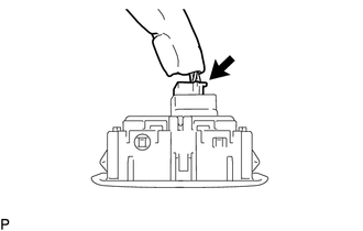
13. REMOVE REAR POWER SEAT SWITCH (for Rear Seat)
HINT:
Use the same procedure for both rear power seat switches.
| (a) Detach the 2 claws to remove the rear power seat switch. |
|
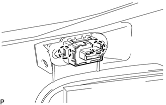
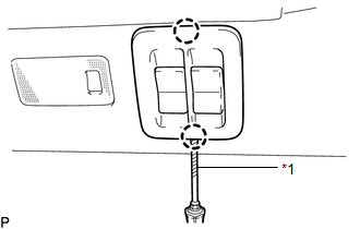
14. REMOVE NO. 2 FOLD SEAT SWITCH ASSEMBLY (for Rear Side)
| (a) Using a screwdriver, detach the 2 claws. HINT: Tape the screwdriver tip before use. |
|
| (b) Disconnect the connector to remove the No. 2 fold seat switch assembly. |
|
READ NEXT:
 Inspection
INSPECTION PROCEDURE 1. INSPECT NO. 1 FOLD SEAT SWITCH ASSEMBLY (for Front Side) (a) Measure the resistance according to the value(s) in the table below. Standard Resistance: Tester Connection
Installation
INSTALLATION PROCEDURE 1. INSTALL NO. 2 FOLD SEAT SWITCH ASSEMBLY (for Rear Side) (a) Connect the connector. (b) Attach the 2 claws to install the No. 2 fold seat switch assembly.
SEE MORE:
Data List / Active Test
DATA LIST / ACTIVE TEST NOTICE: In the table below, the values listed under "Normal Condition" are reference values. Do not depend solely on these reference values when deciding whether a part is faulty or not. HINT: Using the Techstream to read the Data List allows the values or states of switches,
Rough Idling
DESCRIPTION Problem Symptom Suspected Area Trouble Area
Engine speed fluctuation due to abnormal combustion
Idle speed too low or high
Strong engine vibration due to above symptoms
Ignition malfunction
Deviation in air fuel ratio (Excessive or insufficient intake air volume
