Lexus NX: Removal
REMOVAL
CAUTION / NOTICE / HINT
CAUTION:
Wear protective gloves. Sharp areas on the parts may injure your hands.
PROCEDURE
1. REMOVE REAR SEATBACK ASSEMBLY LH
(a) for Manual Seat:
Click here .gif)
(b) for Power Seat:
Click here
2. REMOVE REAR SEATBACK ASSEMBLY RH
(a) for Manual Seat:
Click here
(b) for Power Seat:
Click here
3. REMOVE REAR SEATBACK COVER
Click here
4. REMOVE REAR SEATBACK BOARD CARPET ASSEMBLY RH (for RH Side)
Click here
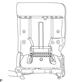
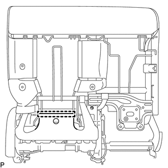
5. REMOVE SEAT HEATER CONTROL SUB-ASSEMBLY (for RH Side)
(a) for Manual Seat:
| (1) Detach the hook. |
|
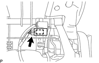
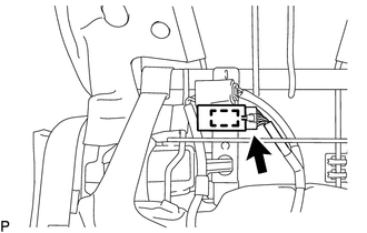
| (2) Disconnect the connector. |
|
(3) Detach the clamp and remove the seat heater control sub-assembly.
(b) for Power Seat:
| (1) Detach the hook. |
|
| (2) Disconnect the connector. |
|
(3) Detach the clamp and remove the seat heater control sub-assembly.
6. REMOVE REAR SEATBACK BOARD CARPET ASSEMBLY LH (for LH Side)
Click here
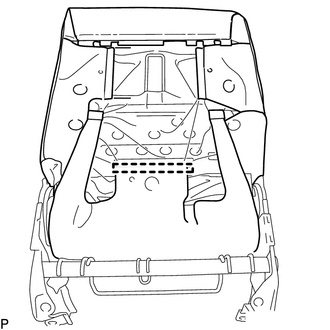
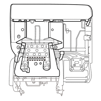
7. REMOVE SEAT HEATER CONTROL SUB-ASSEMBLY (for LH Side)
(a) for Manual Seat:
| (1) Detach the hook. |
|
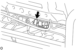
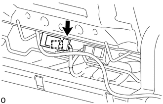
| (2) Disconnect the connector. |
|
(3) Detach the clamp and remove the seat heater control sub-assembly.
(b) for Power Seat:
| (1) Detach the hook. |
|
| (2) Disconnect the connector. |
|
(3) Detach the clamp and remove the seat heater control sub-assembly.
READ NEXT:
 Installation
INSTALLATION CAUTION / NOTICE / HINT CAUTION: Wear protective gloves. Sharp areas on the parts may injure your hands. PROCEDURE 1. INSTALL SEAT HEATER CONTROL SUB-ASSEMBLY (for LH Side) (a) for Manual
Seat Heater Switch(for Rear Seat)
ComponentsCOMPONENTS ILLUSTRATION *1 CONSOLE BOX REGISTER ASSEMBLY *2 REAR CONSOLE END PANEL SUB-ASSEMBLY *3 REFRESHING SEAT SWITCH *4 DUCT RemovalREMOVAL PROCEDURE 1. REMOVE
SEE MORE:
Fuel Level Sensor "A" Circuit Range / Performance (P0461)
DESCRIPTION The fuel sender gauge is located inside the fuel tank and measures the amount of fuel. The fuel sender gauge converts the fuel level in the fuel tank into a output value, and outputs this value. The ECM determines when it is necessary to refuel the vehicle based on changes in the output
Inspection
INSPECTION PROCEDURE 1. INSPECT NO. 1 VALVE ROCKER ARM SUB-ASSEMBLY (a) Turn the roller by hand and check that it turns smoothly. If the roller does not turn smoothly, replace the No. 1 valve rocker arm sub-assembly. 2. INSPECT VALVE LASH ADJUSTER ASSEMBLY NOTICE:
Keep the adjuster free from dirt
