Lexus NX: Removal
REMOVAL
PROCEDURE
1. REMOVE REAR SEAT ASSEMBLY (for Manual Seat)
Click here .gif)
2. REMOVE REAR SEAT ASSEMBLY (for Power Seat)
Click here
3. REMOVE REAR SEAT INNER WITH CENTER BELT ASSEMBLY RH
| (a) for Manual Seat: (1) w/o Seat Heater System:
(2) w/ Seat Heater System:
|
|
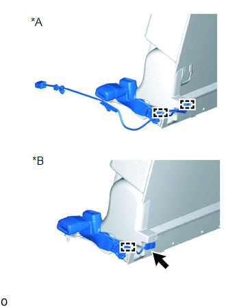
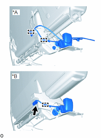
(b) for Power Seat:
| (1) Disconnect the connector. |
|
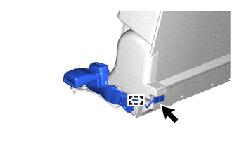
(2) Using a clip remover, detach the wire harness clamp.
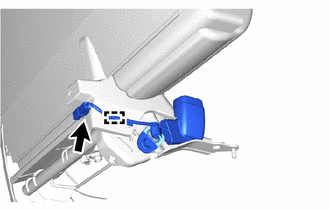
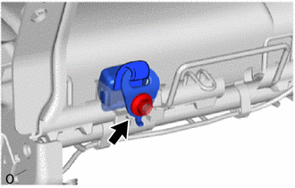
| (c) Remove the bolt. |
|
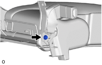
| (d) Detach the 2 hooks and remove the rear seat inner with center belt assembly RH. |
|
4. REMOVE REAR SEAT INNER BELT ASSEMBLY LH
| (a) for Manual Seat: (1) w/o Seat Heater System:
(2) w/ Seat Heater System:
|
|
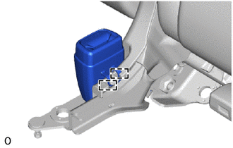
(b) for Power Seat:
| (1) Disconnect the connector. |
|
(2) Using a clip remover, detach the wire harness clamp.
| (c) Remove the bolt. |
|
| (d) Detach the 2 hooks and remove the rear seat inner belt assembly LH. |
|
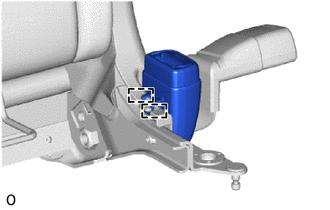
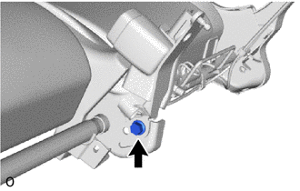
5. REMOVE REAR SEAT CENTER LAP TYPE BELT ASSEMBLY LH
| (a) Remove the nut. |
|
(b) Remove the rear seat center lap type belt assembly LH from the rear seat belt holder.
READ NEXT:
 Inspection
INSPECTION PROCEDURE 1. INSPECT REAR SEAT INNER WITH CENTER BELT ASSEMBLY RH (a) for Manual Seat: (1) w/o Seat Heater System: Measure the resistance according to the value(s) in the table below. St
Installation
INSTALLATION PROCEDURE 1. INSTALL REAR SEAT CENTER LAP TYPE BELT ASSEMBLY LH (a) Install the rear seat center lap type belt assembly LH with the nut. Torque: 42 N·m {428 kgf·cm, 31 ft·lbf} NOTI
SEE MORE:
Parts Location
PARTS LOCATION ILLUSTRATION *1 INNER REAR VIEW MIRROR ASSEMBLY - GARAGE DOOR OPENER *2 INSTRUMENT PANEL JUNCTION BLOCK ASSEMBLY - ECU-IG NO. 3 FUSE *3 NO.1 ENGINE ROOM JUNCTION BLOCK ASSEMBLY - ECU-B NO. 1 FUSE - -
Parts Location
PARTS LOCATION ILLUSTRATION *1 FRONT ABSORBER CONTROL ACTUATOR RH (FRONT SHOCK ABSORBER ASSEMBLY RH) *2 FRONT ABSORBER CONTROL ACTUATOR LH (FRONT SHOCK ABSORBER ASSEMBLY LH) *3 REAR ABSORBER CONTROL ACTUATOR RH (REAR SHOCK ABSORBER ASSEMBLY RH) *4 REAR ABSORBER CONTROL ACTUATOR L
