Lexus NX: Removal
REMOVAL
CAUTION / NOTICE / HINT
HINT:
- Use the same procedure for the RH and LH sides.
- The procedure listed below is for the LH side.
PROCEDURE
1. PRECAUTION
NOTICE:
After the power switch is turned off, there may be a waiting time before disconnecting the negative (-) auxiliary battery terminal.
Click here .gif)
2. REMOVE DECK BOARD ASSEMBLY
Click here
3. REMOVE NO. 3 DECK BOARD SUB-ASSEMBLY
Click here
4. REMOVE REAR DECK FLOOR BOX
Click here
5. REMOVE DECK FLOOR BOX LH
Click here
6. DISCONNECT CABLE FROM NEGATIVE AUXILIARY BATTERY TERMINAL
CAUTION:
Wait at least 90 seconds after disconnecting the cable from the auxiliary battery negative (-) terminal to disable the SRS system.
7. REMOVE REAR SEAT ASSEMBLY
-
for Manual Seat:
Click here
-
for Power Seat:
Click here
8. REMOVE TONNEAU COVER ASSEMBLY
Click here
9. REMOVE NO. 2 DECK BOARD SUB-ASSEMBLY
Click here
10. REMOVE DECK FLOOR BOX LH
Click here
11. REMOVE DECK FLOOR BOX RH
Click here
12. REMOVE NO. 1 TOOL BOX SUB-ASSEMBLY
Click here
13. REMOVE NO. 2 TOOL BOX SUB-ASSEMBLY
Click here
14. REMOVE REAR FLOOR FINISH PLATE
Click here
15. REMOVE BATTERY SERVICE COVER BOARD
-
for Manual Seat:
Click here
-
for Power Seat:
Click here
16. REMOVE NO. 1 SEAT LEG ASSEMBLY
-
for Manual Seat:
Click here
-
for Power Seat:
Click here
17. REMOVE REAR DOOR OPENING TRIM WEATHERSTRIP LH
Click here
18. REMOVE ROPE HOOK ASSEMBLY
Click here
19. REMOVE LUGGAGE HOLD BELT STRIKER ASSEMBLY
Click here
20. REMOVE NO. 1 LUGGAGE COMPARTMENT TRIM HOOK
Click here
21. REMOVE UPPER DECK TRIM SIDE BOARD LH
Click here
22. REMOVE DECK TRIM SIDE PANEL ASSEMBLY LH
Click here
23. REMOVE INNER ROOF SIDE GARNISH ASSEMBLY LH
Click here
24. REMOVE REAR NO. 1 SEAT OUTER BELT ASSEMBLY LH
| (a) Remove the bolt and nut in the order shown in the illustration. |
|
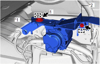
(b) Detach the 2 guides and remove the rear No. 1 seat outer belt assembly LH.
25. REMOVE OUTER BELT ANCHOR BRACKET SUB-ASSEMBLY LH
| (a) Remove the 2 bolts. |
|
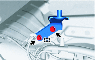
(b) Detach the guide and remove the outer belt anchor bracket sub-assembly LH.
READ NEXT:
 Inspection
INSPECTION PROCEDURE 1. INSPECT REAR NO. 1 SEAT OUTER BELT ASSEMBLY (a) Before installing the rear No. 1 seat outer belt assembly, check the ELR function. NOTICE: Do not disassemble the retractor.
Installation
INSTALLATION CAUTION / NOTICE / HINT HINT:
Use the same procedure for the RH and LH sides.
The procedure listed below is for the LH side.
A bolt without a torque specification is shown in the s
Seat Belt Tension Reducer System
Parts LocationPARTS LOCATION ILLUSTRATION *A w/ Memory - - *1 FRONT SEAT INNER BELT ASSEMBLY RH *2 FRONT SEAT INNER BELT ASSEMBLY LH *3 FRONT SEAT OUTER BELT ASSEMBLY RH *
SEE MORE:
System Description
SYSTEM DESCRIPTION SYSTEM DESCRIPTION (a) The electric parking brake system electronically controls the parking brake lock and release operations using actuators. The main functions are as follows: Functions when vehicle stopped
When the electric parking brake switch (integration control and pane
Rear Right Sensor Malfunction (C1AE9)
DESCRIPTION The rear corner ultrasonic sensor (RR sensor) is installed to the rear bumper. The clearance warning ECU assembly detects obstacles based on signals received from the rear corner ultrasonic sensor (RR sensor). If the rear corner ultrasonic sensor (RR sensor) has an open circuit or other
