Lexus NX: Removal
REMOVAL
CAUTION / NOTICE / HINT
CAUTION:
Wear protective gloves. Sharp areas on the parts may injure your hands.
PROCEDURE
1. REMOVE NO. 3 DECK BOARD SUB-ASSEMBLY
Click here .gif)
2. REMOVE REAR DECK FLOOR BOX
Click here
3. REMOVE DECK FLOOR BOX LH
Click here
4. PRECAUTION
CAUTION:
Be sure to read Precaution thoroughly before servicing.
Click here
NOTICE:
After the power switch is turned off, there may be a waiting time before disconnecting the negative (-) auxiliary battery terminal.
Click here
5. DISCONNECT CABLE FROM NEGATIVE AUXILIARY BATTERY TERMINAL
CAUTION:
Wait at least 90 seconds after disconnecting the cable from the negative (-) auxiliary battery terminal to disable the SRS system.
(a) Loosen the nut and disconnect the cable from the negative (-) auxiliary battery terminal.
6. REMOVE FRONT SEAT ASSEMBLY LH
Click here
7. REMOVE SEAT HEATER CONTROL SUB-ASSEMBLY LH (w/ Seat Heater System)
Click here
8. REMOVE SEAT POSITION AIRBAG SENSOR
| (a) Disconnect the connector. |
|
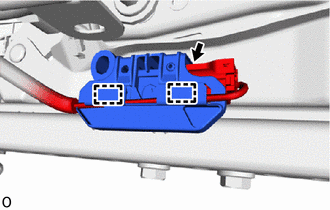
(b) Detach the 2 wire harness clamps.
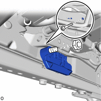
| (c) Using a T30 "TORX" socket wrench, remove the "TORX" bolt and nut and seat position airbag sensor together with the seat slide position sensor protector. |
|
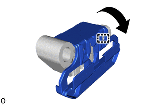
| (d) Detach the guide and remove the seat slide position sensor protector from the seat position airbag sensor. |
|
READ NEXT:
 Installation
INSTALLATION CAUTION / NOTICE / HINT CAUTION: Wear protective gloves. Sharp areas on the parts may injure your hands. PROCEDURE 1. INSTALL SEAT POSITION AIRBAG SENSOR (a) Align the adjustment suppo
Components
COMPONENTS ILLUSTRATION *1 DECK FLOOR BOX LH *2 NO. 3 DECK BOARD SUB-ASSEMBLY *3 REAR DECK FLOOR BOX *4 AUXILIARY BATTERY NEGATIVE TERMINAL N*m (kgf*cm, ft.*lbf): Specified
SEE MORE:
Drive Motor "B" Control Module (P0A1C-118)
DTC SUMMARY MALFUNCTION DESCRIPTION These DTCs indicate that an overvoltage in the inverter has occurred. The cause of this malfunction may be one of the following: Internal inverter malfunction
Inverter internal circuit malfunction
Malfunction in ECU that controls the inverter
DESCRIPTION F
Installation
INSTALLATION PROCEDURE 1. INSTALL BATTERY COOLING BLOWER ASSEMBLY LH CAUTION: Wear insulated gloves and use insulated tools. (a) Install the battery cooling blower assembly LH with the 3 nuts. Torque: 7.5 N·m {76 kgf·cm, 66 in·lbf} (b) Connect the wire harness clamp and connector. 2. INSTALL BAT
