Lexus NX: Removal
REMOVAL
PROCEDURE
1. REMOVE NO. 3 DECK BOARD SUB-ASSEMBLY
Click here .gif)
2. REMOVE REAR DECK FLOOR BOX
Click here
3. REMOVE DECK FLOOR BOX LH
Click here
4. PRECAUTION
CAUTION:
Be sure to read Precaution thoroughly before servicing.
Click here
NOTICE:
After the power switch is turned off, there may be a waiting time before disconnecting the negative (-) auxiliary battery terminal.
Click here
5. DISCONNECT CABLE FROM NEGATIVE AUXILIARY BATTERY TERMINAL
CAUTION:
Wait at least 90 seconds after disconnecting the cable from the negative (-) auxiliary battery terminal to disable the SRS system.
(a) Loosen the nut and disconnect the cable from the negative (-) auxiliary battery terminal.
6. REMOVE LOWER NO. 3 STEERING WHEEL COVER
(a) Using a screwdriver, insert the screwdriver into the cutout of the lower No. 3 steering wheel cover and detach the claw and guide to remove the lower No. 3 steering wheel cover.
HINT:
Tape the screwdriver tip before use.
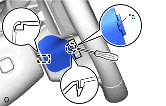
| *a | Cutout |
.png) | Protective Tape |
7. REMOVE LOWER NO. 2 STEERING WHEEL COVER
(a) Using a screwdriver, insert the screwdriver into the cutout of the lower No. 2 steering wheel cover and detach the claw and guide to remove the lower No. 2 steering wheel cover.
HINT:
Tape the screwdriver tip before use.
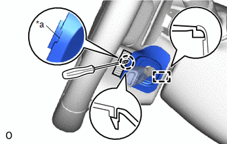
| *a | Cutout |
| | Protective Tape |
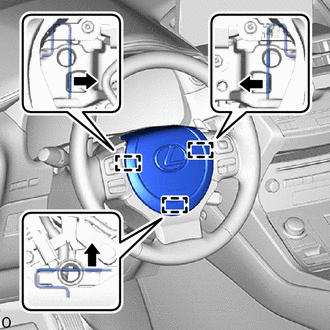
8. REMOVE STEERING PAD ASSEMBLY
CAUTION:
When storing the steering pad assembly, keep the airbag deployment side facing upward.
(a) Check that the power switch is off.
(b) Check that the cable is disconnected from the negative (-) auxiliary battery terminal.
CAUTION:
Wait at least 90 seconds after disconnecting the cable from the negative (-) auxiliary battery terminal to disable the SRS system.
| (c) Using a T25H "TORX" screwdriver, push in the 3 torsion springs to detach the 3 pins and remove the steering pad assembly. NOTICE:
HINT: Insert the T25H "TORX" screwdriver into the installation areas of the lower No. 2 steering wheel cover and lower No. 3 steering wheel cover. |
|
(d) Tilt the steering pad assembly toward the seat and support it with one hand.
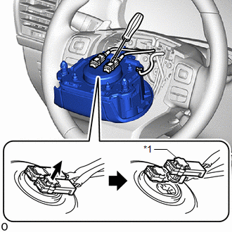
| *1 | Connector Lock |
| | Protective Tape |
(e) Disconnect the horn connector.
(f) Using a screwdriver, release the connector lock and disconnect the airbag connector.
NOTICE:
When disconnecting any airbag connector, take care not to damage the airbag wire harness.
HINT:
- Tape the screwdriver tip before use.
- Use the same procedure to disconnect the airbag connector on the other side.
READ NEXT:
 Installation
INSTALLATION PROCEDURE 1. INSTALL STEERING PAD ASSEMBLY (a) Check that the power switch is off. (b) Check that the cable is disconnected from the negative (-) auxiliary battery terminal. CAUTION: Wait
Disposal
DISPOSAL CAUTION / NOTICE / HINT CAUTION: Before performing pre-disposal deployment of any SRS part, review and closely follow all applicable environmental and hazardous material regulations. Pre-disp
SEE MORE:
Components
COMPONENTS ILLUSTRATION *1 SIDE MUDGUARD SUB-ASSEMBLY LH *2 GROMMET ● Non-reusable part - - ILLUSTRATION *1 NO. 3 MOULDING TAPE - - ● Non-reusable part - -
Sending Malfunction (Navigation to APGS) (U0073,U0100,U0129,U0140,U0155,U0164,U0198,U023B,U0265,U0293,U1110)
DESCRIPTION These DTCs are stored when a malfunction occurs in the CAN communication circuit. DTC No. Detection Item DTC Detection Condition Trouble Area U0073 Sending Malfunction (Navigation to APGS) CAN bus connection error CAN communication system U0100 Engine ECU Communi
