Lexus NX: Removal
REMOVAL
PROCEDURE
1. REMOVE DECK BOARD ASSEMBLY
Click here .gif)
2. REMOVE NO. 3 DECK BOARD SUB-ASSEMBLY
Click here
3. REMOVE REAR DECK FLOOR BOX
Click here
4. REMOVE DECK FLOOR BOX LH
Click here
5. PRECAUTION
CAUTION:
Be sure to read Precaution thoroughly before serving.
Click here
NOTICE:
After turning the power switch off, there may be a waiting time before disconnecting the negative (-) auxiliary battery terminal.
Click here
6. DISCONNECT CABLE FROM NEGATIVE AUXILIARY BATTERY TERMINAL
CAUTION:
- Wait at least 90 seconds after disconnecting the cable from the negative (-) auxiliary battery terminal to disable the SRS system.
- If the airbag deploys for any reason. it may cause a serious accident.
7. REMOVE INSTRUMENT PANEL FINISH PLATE
Click here
8. REMOVE MULTI-DISPLAY ASSEMBLY WITH BRACKET
Click here
9. REMOVE UPPER NO. 1 CONSOLE PANEL GARNISH
Click here
10. REMOVE UPPER NO. 2 CONSOLE PANEL GARNISH
Click here
11. REMOVE INSTRUMENT SIDE PANEL RH
Click here
12. REMOVE INSTRUMENT SIDE PANEL LH
Click here
13. REMOVE NO. 1 INSTRUMENT PANEL SAFETY PAD SUB-ASSEMBLY
Click here
14. REMOVE NO. 1 SWITCH HOLE BASE
Click here
15. REMOVE NO. 1 INSTRUMENT PANEL UNDER COVER SUB-ASSEMBLY
Click here
16. REMOVE LOWER NO. 1 INSTRUMENT PANEL FINISH PANEL
Click here
17. REMOVE NO. 2 INSTRUMENT PANEL SAFETY PAD SUB-ASSEMBLY
Click here
18. REMOVE CENTER INSTRUMENT CLUSTER FINISH PANEL ASSEMBLY
Click here
19. REMOVE SHIFT LEVER KNOB SUB-ASSEMBLY
Click here
20. REMOVE CONSOLE ARMREST ASSEMBLY
Click here
21. REMOVE UPPER REAR CONSOLE PANEL
Click here
22. REMOVE UPPER REAR CONSOLE PANEL SUB-ASSEMBLY
Click here
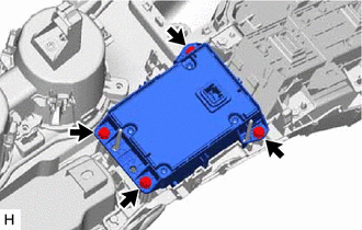
23. REMOVE REMOTE OPERATION CONTROLLER ASSEMBLY
| (a) Remove the 4 bolts and remote operation controller assembly. |
|
READ NEXT:
 Installation
INSTALLATION PROCEDURE 1. INSTALL REMOTE OPERATION CONTROLLER ASSEMBLY (a) Install the remote operation controller assembly with the 4 bolts. 2. INSTALL UPPER REAR CONSOLE PANEL SUB-ASSEMBLY Click her
Telephone Microphone Assembly
ComponentsCOMPONENTS ILLUSTRATION *1 TELEPHONE MICROPHONE ASSEMBLY - -
SEE MORE:
Air Outlet Damper Control Servo Motor Circuit (B1443)
DESCRIPTION The No. 1 air conditioning radiator damper servo sub-assembly (mode) sends pulse signals to inform the air conditioning amplifier assembly of the damper position. The air conditioning amplifier assembly activates the motor (normal, reverse) based on the signals to move the No. 1 air cond
Components
COMPONENTS ILLUSTRATION *1 DECK FLOOR BOX LH *2 NO. 3 DECK BOARD SUB-ASSEMBLY *3 REAR DECK FLOOR BOX *4 NEGATIVE AUXILIARY BATTERY TERMINAL N*m (kgf*cm, ft.*lbf): Specified torque - - ILLUSTRATION *A for 8 Inch *B for 10.3 Inch *1 CENTER INSTRUMENT C
