Lexus NX: Removal
REMOVAL
CAUTION / NOTICE / HINT
NOTICE:
- When the brake pedal is first depressed after replacing the brake pads or pushing back the disc brake piston, DTC C1214 may be output. As there is no malfunction, clear the DTC.
- While the auxiliary battery is connected, even if the power switch is off, the brake control system activates when the brake pedal is depressed or the door courtesy switch is turned on. Therefore, even if only brake shoes are to be removed and installed, be sure to perform the Disable Brake Control procedure and disconnect the cable from the negative (-) terminal of the auxiliary battery before beginning work.
HINT:
- Use the same procedure for the RH and LH sides.
- The procedure listed below is for the LH side.
PROCEDURE
1. PRECAUTION
NOTICE:
After turning the power switch off, waiting time may be required before disconnecting the cable from the negative (-) auxiliary battery terminal. Therefore, make sure to read the disconnecting the cable from the negative (-) auxiliary battery terminal notice before proceeding with work.
(Click here .gif) )
)
2. DISABLE BRAKE CONTROL
Click here
3. REMOVE FRONT WHEEL
Click here
4. REMOVE FRONT AXLE SHAFT NUT LH
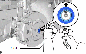
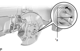
(a) Using SST and a hammer, unstake the staked part of the front axle shaft nut.
SST: 09930-00010
09931-00010
09931-00020
NOTICE:
Loosen the staked part of the front axle shaft nut completely, otherwise the screw of the drive shaft may be damaged.
(b) While applying the brakes, remove the front axle shaft nut.
5. DISCONNECT FRONT SPEED SENSOR LH (w/ AVS)
Click here
6. DISCONNECT FRONT SPEED SENSOR LH (w/o AVS)
Click here
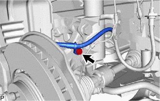
7. DISCONNECT FRONT FLEXIBLE HOSE (w/o AVS)
| (a) Remove the bolt and disconnect the flexible hose. |
|
8. DISCONNECT FRONT DISC BRAKE CALIPER ASSEMBLY LH
Click here
9. REMOVE FRONT DISC
Click here
10. DISCONNECT TIE ROD END SUB-ASSEMBLY LH
Click here
11. DISCONNECT FRONT LOWER NO. 1 SUSPENSION ARM SUB-ASSEMBLY LH
| (a) Remove the bolt and 2 nuts. |
|
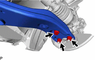
(b) Disconnect the front lower No. 1 suspension arm sub-assembly LH from the lower ball joint assembly LH.
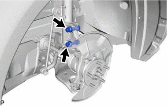
12. REMOVE FRONT AXLE ASSEMBLY LH
| (a) Remove the 2 bolts and 2 nuts, and disconnect the front shock absorber assembly with coil spring from the steering knuckle. HINT: While fixing the nuts in place, loosen and remove the bolts. |
|
| (b) Put matchmarks on the drive shaft and front axle hub sub-assembly. |
|
(c) Using a plastic-faced hammer, remove the steering knuckle assembly.
NOTICE:
Be careful not to damage the front axle outboard joint boot and speed sensor rotor. Do not excessively push out the drive shaft from the axle assembly.
13. REMOVE FRONT AXLE HUB SUB-ASSEMBLY LH
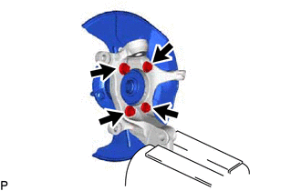
(a) Secure the front axle assembly in a vise.
NOTICE:
When using a vise, do not overtighten it.
(b) Remove the 4 bolts and front axle hub sub-assembly from the steering knuckle.
NOTICE:
Do not place the hub and bearing's magnet rotor side so that it is facing downward, and do not allow the magnet rotor side to become damaged or contact foreign matter.
(c) Remove the front brake dust cover from the steering knuckle.
READ NEXT:
 Installation
INSTALLATION CAUTION / NOTICE / HINT NOTICE:
When the brake pedal is first depressed after replacing the brake pads or pushing back the disc brake piston, DTC C1214 may be output. As there is no ma
Components
COMPONENTS ILLUSTRATION *1 FRONT AXLE HUB BOLT LH *2 FRONT DISC *3 FRONT DISC BRAKE CALIPER ASSEMBLY LH - - N*m (kgf*cm, ft.*lbf): Specified torque ● Non-reusable part
SEE MORE:
Removal
REMOVAL PROCEDURE 1. PRECAUTION NOTICE: After the power switch is turned off, there may be a waiting time before disconnecting the negative (-) auxiliary battery terminal. Click here 2. REMOVE NO. 3 DECK BOARD SUB-ASSEMBLY Click here 3. REMOVE REAR DECK FLOOR BOX Click here 4. REMOVE DECK FLOO
Deceleration Sensor (C1245)
DESCRIPTION The parking brake ECU assembly receives vehicle tilt information from the deceleration sensor (airbag ECU assembly) via CAN communication. DTC No. Detection Item DTC Detection Condition Trouble Area Memory Note C1245 Deceleration Sensor One of the following condition
