Lexus NX: Removal
REMOVAL
PROCEDURE
1. DRAIN ENGINE COOLANT
Click here .gif)
2. REMOVE FRONT BUMPER REINFORCEMENT SUB-ASSEMBLY
Click here
3. DISCONNECT HOOD LOCK ASSEMBLY
| (a) Detach the 2 clamps and disconnect the hood lock connector. |
|
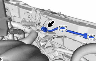
| (b) Remove the 3 bolts and disconnect the hood lock assembly from the upper radiator support sub-assembly. |
|
(c) Detach the clamp and disconnect the hood lock control cable assembly from the upper radiator support sub-assembly.
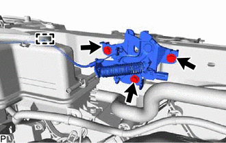
4. REMOVE NO. 6 INVERTER BRACKET
| (a) Remove the 2 bolts and No. 6 inverter bracket from upper radiator support sub-assembly. |
|
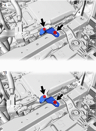
5. REMOVE UPPER RADIATOR SUPPORT SUB-ASSEMBLY
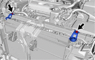
| (a) Detach the 3 claws and remove the front radiator side air guide plate LH from the upper radiator support sub-assembly. |
|
(b) Detach the 3 claws and disconnect the front radiator side air guide plate RH from the upper radiator support sub-assembly.
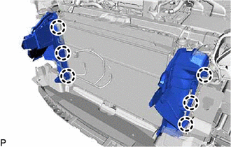
| (c) Detach the 3 clamps and disconnect the 2 connectors and wire harness from the upper radiator support sub-assembly. |
|
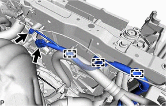
| (d) Remove the 2 bolts and 2 radiator support sub-assemblies from the upper radiator support sub-assembly. |
|
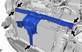
| (e) Remove the 5 bolts and upper radiator support sub-assembly. |
|
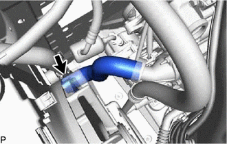
6. DISCONNECT NO. 2 WATER BY-PASS HOSE
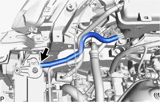
(a) Slide the clip and disconnect the No. 2 water by-pass hose from the radiator assembly.
7. DISCONNECT WATER BY-PASS PIPE
| (a) Slide the clip and disconnect the water by-pass pipe from the radiator reservoir. |
|
| (b) Slide the clip and disconnect the No. 5 water by-pass hose from the radiator assembly. |
|
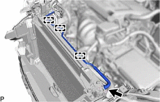
(c) Detach the 3 clamps and disconnect the water by-pass pipe from the fan shroud.
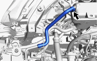
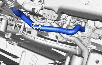
8. DISCONNECT NO. 2 RADIATOR HOSE
| (a) Slide the clip and disconnect the No. 2 radiator hose from the radiator assembly. |
|
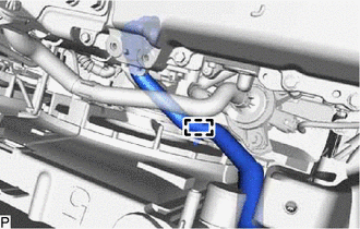
9. DISCONNECT NO. 1 RADIATOR HOSE
| (a) Detach the clamp and disconnect the No. 1 radiator hose from the fan shroud. |
|
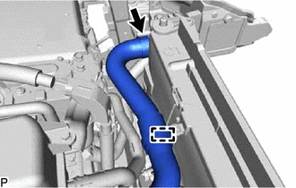
(b) Slide the clip and disconnect the No. 1 radiator hose from the radiator assembly.
10. DISCONNECT NO. 2 INVERTER COOLING HOSE
| (a) Detach the clamp and disconnect the No. 2 inverter cooling hose from the fan shroud. |
|
11. DISCONNECT NO. 4 INVERTER COOLING HOSE
(a) Detach the clamp and disconnect the No. 4 inverter cooling hose from the fan shroud.
12. DISCONNECT NO. 5 INVERTER COOLING HOSE
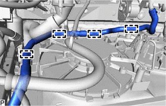
(a) Detach the 4 clamps and disconnect the No. 5 inverter cooling hose from the fan shroud.
13. REMOVE NO. 2 FAN SHROUD
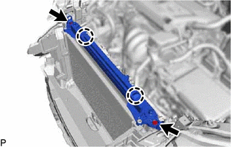
(a) Remove the 2 bolts.
(b) Detach the 2 claws and remove the No. 2 fan shroud from the radiator assembly.
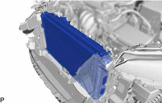
14. REMOVE RADIATOR ASSEMBLY WITH FAN SHROUD
| (a) Remove the radiator assembly with fan shroud from the vehicle. NOTICE: Do not damage the core of the cooler condenser assembly and radiator assembly. |
|
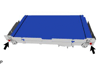
15. REMOVE RADIATOR ASSEMBLY
| (a) Remove the 2 bolts and radiator assembly from the fan shroud with cooling fan. NOTICE: Do not damage the core of the radiator assembly. |
|
16. REMOVE RADIATOR SUPPORT CUSHION
(a) Remove the 2 radiator support cushions from the 2 radiator support sub-assemblies.
17. REMOVE LOWER RADIATOR SUPPORT
(a) Remove the 2 lower radiator supports from the fan shroud.
READ NEXT:
 Installation
INSTALLATION PROCEDURE 1. INSTALL LOWER RADIATOR SUPPORT (a) Install the 2 lower radiator supports to the fan shroud. 2. INSTALL RADIATOR SUPPORT CUSHION (a) Install the 2 radiator support cushions to
Relay
On-vehicle InspectionON-VEHICLE INSPECTION PROCEDURE 1. INSPECT COOLING FAN RELAY (FAN NO. 1) (a) Measure the resistance according to the value(s) in the table below. Standard Resistance: Test
Thermostat
ComponentsCOMPONENTS ILLUSTRATION *1 THERMOSTAT *2 WATER INLET *3 GASKET - - N*m (kgf*cm, ft.*lbf): Specified torque ● Non-reusable part RemovalREMOVAL PROCEDURE
SEE MORE:
Reassembly
REASSEMBLY PROCEDURE 1. INSTALL ENGINE HOOD LOCK STRIKER ASSEMBLY (a) Attach the guide. (b) Install the engine hood lock striker assembly with the 2 bolts. Torque: 8.0 N·m {82 kgf·cm, 71 in·lbf} 2. INSTALL RADIATOR SUPPORT OPENING COVER Click here 3. INSTALL HOOD AUXILIARY CATCH HOOK ASSEMBL
Removal
REMOVAL CAUTION / NOTICE / HINT NOTICE:
When the brake pedal is first depressed after replacing the brake pads or pushing back the disc brake piston, DTC C1214 may be output. As there is no malfunction, clear the DTC.
While the auxiliary battery is connected, even if the power switch is off, th
