Lexus NX: Replacement
REPLACEMENT
CAUTION / NOTICE / HINT
NOTICE:
- When the brake pedal is first depressed after replacing the brake pads or pushing back the disc brake piston, DTC C1214 may be output. As there is no malfunction, clear the DTC.
- While the auxiliary battery is connected, even if the power switch is off, the brake control system activates when the brake pedal is depressed or the door courtesy switch is turned on. Therefore, even if only brake shoes are to be removed and installed, be sure to perform the Disable Brake Control procedure and disconnect the cable from the negative (-) terminal of the auxiliary battery before beginning work.
HINT:
- Use the same procedure for the RH and LH sides.
- The procedure listed below is for the LH side.
PROCEDURE
1. PRECAUTION
NOTICE:
After turning the power switch off, waiting time may be required before disconnecting the cable from the negative (-) auxiliary battery terminal. Therefore, make sure to read the disconnecting the cable from the negative (-) auxiliary battery terminal notice before proceeding with work.
(Click here .gif) )
)
2. DISABLE BRAKE CONTROL
Click here
3. REMOVE FRONT WHEEL
Click here
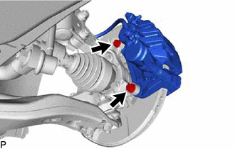
4. DISCONNECT FRONT DISC BRAKE CALIPER ASSEMBLY LH
| (a) Remove the 2 bolts and disconnect the front disc brake caliper assembly from the steering knuckle. NOTICE: Use wire or an equivalent tool to keep the brake caliper from hanging down by the flexible hose. |
|
5. REMOVE FRONT DISC
Click here
6. REMOVE FRONT AXLE HUB BOLT LH
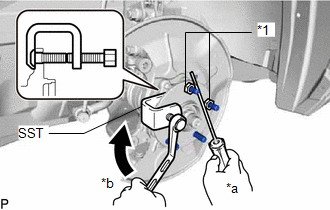
| *1 | Nut |
| *a | Hold |
| *b | Turn |
(a) Temporarily install 2 nuts and 2 washers to the front axle hub bolt as shown in the illustration.
(b) Using SST and a screwdriver or an equivalent tool to hold the front axle, remove the front axle hub bolt.
SST: 09611-12010
7. INSTALL FRONT AXLE HUB BOLT LH
| (a) Install a washer and nut to a new front axle hub bolt as shown in the illustration. |
|
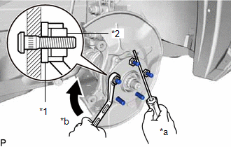
(b) Using a screwdriver or an equivalent tool to hold the front axle, install the hub bolt by tightening the nut.
(c) Remove the nut and plate washer.
8. INSTALL FRONT DISC
Click here
9. CONNECT FRONT DISC BRAKE CALIPER ASSEMBLY LH
(a) Connect the front disc brake caliper assembly to the steering knuckle with the 2 bolts.
Torque:
106.8 N·m {1089 kgf·cm, 79 ft·lbf}
10. INSTALL FRONT WHEEL
Click here
11. CONNECT CABLE TO NEGATIVE AUXILIARY BATTERY TERMINAL
(a) Connect the cable to the negative (-) auxiliary battery terminal and tighten the nut.
Torque:
5.4 N·m {55 kgf·cm, 48 in·lbf}
READ NEXT:
 Components
COMPONENTS ILLUSTRATION *A w/ AVS - - *1 REAR AXLE CARRIER SUB-ASSEMBLY LH *2 REAR HEIGHT CONTROL SENSOR SUB-ASSEMBLY LH *3 REAR NO. 1 SHOCK ABSORBER BRACKET LH *4 REAR N
Removal
REMOVAL CAUTION / NOTICE / HINT NOTICE:
When the brake pedal is first depressed after replacing the brake pads or pushing back the disc brake piston, DTC C1214 may be output. As there is no malfunc
SEE MORE:
Installation
INSTALLATION PROCEDURE 1. INSTALL VEHICLE APPROACHING SPEAKER CONTROLLER (a) Connect the connector. (b) Attach the hook to install the vehicle approaching speaker controller. NOTICE:
When installing the vehicle approaching speaker controller, take care not to damage it.
Do not reuse a vehicle a
Inspection
INSPECTION PROCEDURE 1. INSPECT REAR NO. 1 SEAT OUTER BELT ASSEMBLY (a) Before installing the rear No. 1 seat outer belt assembly, check the ELR function. NOTICE: Do not disassemble the retractor. (1) When the inclination of the retractor is 15° or less, check that the belt can be pulled from th
